


B-24 SYNCHRONIZATION OF DIGITAL FACILITIES
_ ___________________________________________________________________________________________________________________________
_ ___________________________________________________________________________________________________________________________
_ ___________________________________________________________________________________________________________________________
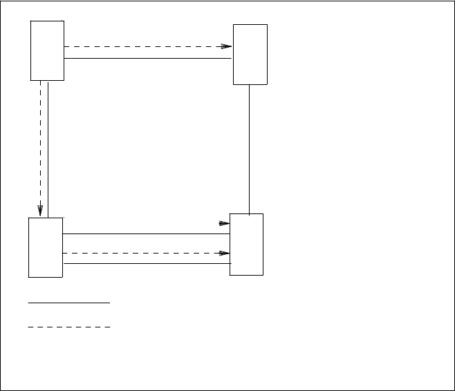
A
. . . . . . . . . . . . . . . . .
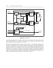
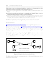
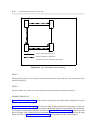
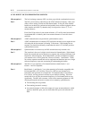
SECONDARY (BACKUP) FREQUENCY REFERENCE
C
D
. . . . . . . . . . . . . . . . . . . . . . . . . . . . . . . . . . .
DIGITAL TRANSMISSION FACILITY
PRIMARY FREQUENCY REFERENCE
B
Figure B-16. Less Than Optimal Diverse Routing
RULE 5:
Obtaining both primary and secondary synchronization facilities from within the same transmission cable
should be minimized.
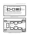
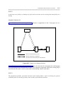
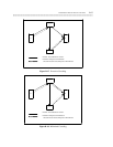
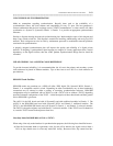
RULE 6:
The total number of cascade node connections from the referenced node should be minimized.
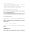
EXAMPLE FOR RULE 6
Figure B-17, Excessive Cascading, shows excessive cascading in that node B derives timing from a source
three transmission facilities away.
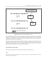
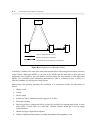
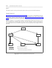
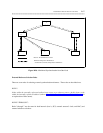
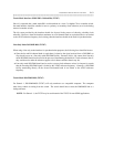
Figure B-18, Minimized Cascading, shows less cascading in that node B derives timing from a source two
transmission facilities away. Excessive cascading is undesirable because of intermediate link vulnerability.
For example, an intermediate link failure in node C of figure B-17, Excessive Cascading, would cause node
B to lose timing. Such a failure increases the number of slips between nodes A and B. However, the same
failure in Node C of figure B-18, Minimized Cascading, does not affect node B’s synchronization.