


D-12 COMMUNICATIONS PROTOCOLS
_ ___________________________________________________________________________________________________________________________
_ ___________________________________________________________________________________________________________________________
_ ___________________________________________________________________________________________________________________________
—Requires a ‘‘circuit-switched’’ transmission facility
Applications:
There are two uses of mode 0. They are:
(a) 8-bit PCM voice (no robbed-bit or inband signaling is allowed)
(b) 64-kbps user data.
Description:
With 64-kbps data, nothing is known about the structure of the information in the channel. Therefore, a
64-kbps data channel (DCP I-channel) is required end-to-end. With 64-kbps mu=255 PCM voice, standard
transformations to other channel types such as analog are possible. Therefore, mode-0 data calls require an
end-to-end 64-kbps digital facility, but mode-0 voice calls can use analog, digital, or a combination of both
types of facilities. This distinction of whether the channel is to be used for voice or data is an important
administration consideration.
Note: For DCP applications that use mode 0, the switched facilities are set up/taken down by S-channel
signaling. For DS1 and DMI/BOS applications that use mode-0 channels, the switched facilities (channels)
are seized/dropped by signaling commands on the 24th channel.
Data Mode 1
Capabilities:
—56 kbps
—Full-duplex operation
—Synchronous transmission of user data (slave timing)
—Requires a ‘‘circuit-switched’’ transmission facility
Applications:
There are three distinct uses of mode 1. They consist of one on-premises and two off-premises
applications. They are:
(a) DDS Data Service Unit (DSU) emulation (e.g., on-premises MPDM-switch-MPDM arrangement)
(b) DSU off-premises (e.g., ACCUNET Switched 56-kbps Service)
(c) T1 facilities (e.g., via a CDM, 753 T-MUX, D4/D5 channel bank, or other compatible equipment)
Description:
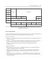
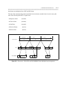
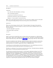
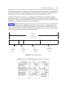
When a data channel is operated in data mode 1, each octet is subdivided into two fields. The first field
consists of the first seven bits (D1-D7). The second or status field consists of bit (D8). The first field
contains either customer data or a control state code which is dependent upon the state of the status bit
(0/1). Figure D-3 depicts the mode 1 field and frame’s organization. The figure also shows how mode 1