


DISTRIBUTED COMMUNICATIONS SYSTEM (DCS) 6-5
_ ______________________________________________________________________________________
_ ______________________________________________________________________________________
_ ______________________________________________________________________________________
(See chapter 9 for detailed permanent connection configurations. The DEFINITY Communications System
System 75 and Generic 1.1 Implementation manual (555-204-654) and the DEFINITY Communications
System System 85 and Generic 2 Feature Descriptions manual (555-104-301) provide permanent
connection implementation details.)
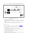
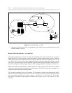
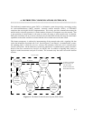
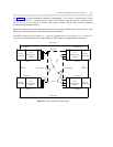
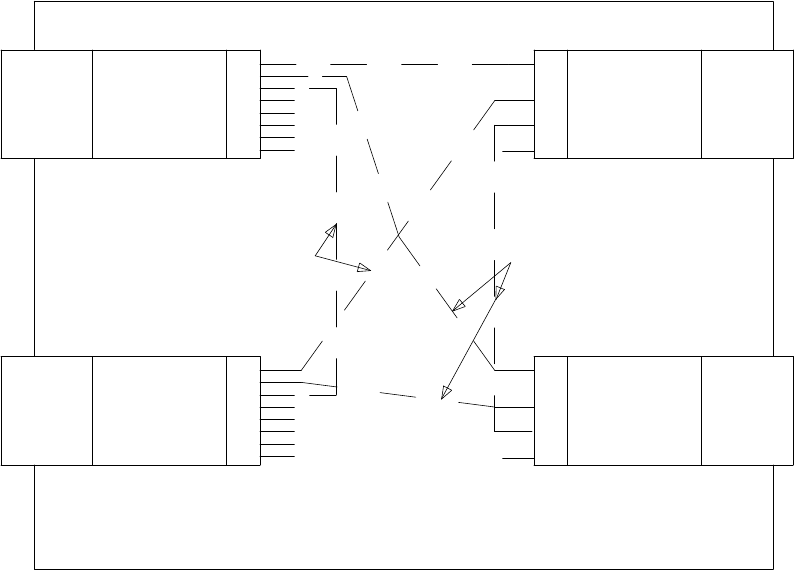
When DCS signaling is channeled through a DS1 port, the signaling channel can be carried over the same
DS1 facility as that which carries voice between the network nodes.
See AT&T Product Interfaces Reference — DEFINITY Communications System Generic 2.1 to Generic 1.1
with DCS for detailed procedures for establishing DS1 DCS channels using permanent connections.
SWITCH
NETWORK
CALL
PROCESSOR &
MEMORY
NODE 1
D
C
I
U
DCIU LINK
1
3
4
D
I
CALL
PROCESSOR &
NODE 2
TIE TRUNKS
TIE TRUNKS
TIE
TRUNKS
TIE
TRUNKS
SYSTEM 85
1
2
3
4
5
6
7
8
2
C
U
MEMORY
SWITCH
NETWORK
1
3
4
I
CALL
PROCESSOR &
2
P
MEMORY
SWITCH
NETWORK
SWITCH
NETWORK
CALL
PROCESSOR &
MEMORY
D
C
I
U
SYSTEM 85
1
2
3
4
5
6
7
8
"DIMENSION" SYSTEM
FP8 (ISSUE 3)
NODE 3 ENDPOINT
SYSTEM 75
DCIU LINKS
DCIU/PI LINKS
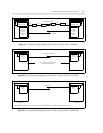
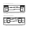
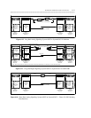
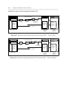
Figure 6-3. Direct Link DCS Connections