


1-14 TRANSMISSION STATES
_ ___________________________________________________________________________________________________________________________
_ ___________________________________________________________________________________________________________________________
_ ___________________________________________________________________________________________________________________________
types of trunk protocols (for example, primary rate interface [PRI] and 24th-channel signaling) use DS1
protocol at layer 1. (See the Trunking section of this chapter for an explanation of these trunk types.)
Inside the switch, data transmission appears in one of two forms. It can be raw bits (digital data), the
physical layer protocols, like DCP and BRI having been stripped at the incoming port and inserted again at
the outgoing port. Or it can be PCM-encoded analog signals (analog transmission via a modem), the signal
having been digitized by a codec at the incoming port.
Layer 2 Protocols
At layer 2, the protocols are given below.
• 8-bit character code between the DTE and the DCE. Depending upon the type of equipment used, the
code can be ASCII, EBCDIC, or any proprietary code set. ASCII code can be sent asynchronously (one
character at a time), or synchronously (one transmission unit, or frame, at a time). EBCDIC is
transmitted synchronously.
• Digital multiplexed interface (DMI) proprietary family of protocols between the originating DCE and
the destination DCE for digital transmission. (For a description of this protocol, see appendix D;
DEFINITY Communications System and System 75 and System 85 DS1/DMI/ISDN PRI Reference, 555-
025-101; and Digital Multiplexed Interface [DMI] Technical Specification, Issue 3.2, 555-025-204.)
• Voice-grade data between the originating DCE and the destination DCE for analog transmission.
Protocol States
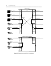
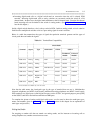
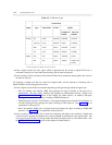
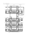
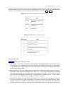
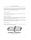
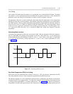
Table 1-3 summarizes the protocols used in switch communication at various points in the transmission
stream. Figure 1-3 illustrates these protocol-states for data transmission.
Table 1-3. Protocol States for Data Communication
_ ___________________________________________________________________________________________________________
Protocols
_ ______________________________________________________________________
Transmission Incoming OSI DTE to DCE to Inside
Type DCE Layer DCE Switch Port Switch
_ ___________________________________________________________________________________________________________
_ ___________________________________________________________________________________________________________
Analog Modem 1 RS-232, RS-449, or V.35 analog PCM
_ _______________________________________________________________________________
2 8- or 10-bit code voice-grade data voice-grade data
_ _____________________________________________________________________________________________
ADU 1 RS-232 ADU proprietary raw bits (digital data)
_ _______________________________________________________________________________
2 asynch 8-bit code asynch 8-bit code DMI
_ ___________________________________________________________________________________________________________
Digital Data Module 1 RS-232, RS-449, or V.35 DCP or BRI raw bits (digital data)
_ _______________________________________________________________________________
2 8-bit code DMI DMI
_ _____________________________________________________________________________________________
DS1 1 any DS1 PCM or
raw bits (digital data)
_ _______________________________________________________________________________
2 8-bit code DMI or voice-grade data DMI or voice-grade data
_ ___________________________________________________________________________________________________________