


TRANSMISSION STATES 1-11
_ ______________________________________________________________________________________
_ ______________________________________________________________________________________
_ ______________________________________________________________________________________
DATA TRANSMISSION
Because of the variety of protocols that can be used in data communication, data transmission has many
more options than voice. To understand the processes that occur at the switch with data transmission, you
must be familiar with the layers of protocol that the switch handles, understand some details about the
protocols used at these layers, and know the points at which these protocols change.
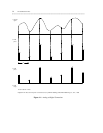
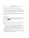
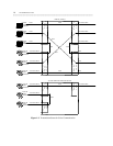
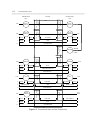
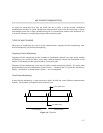
Use figure 1-3 as a pictorial guide through data-transmission state changes. The figure illustrates the flow
of data from data terminal equipment (DTE), like a terminal or host, through data communications
equipment (DCE), like a modem or data module, into a communications system port on the switch. In the
figure, the data flow is shown by solid lines. Below these lines are stated the protocols that are used at
particular points in the data stream.
Note that the figure illustrates data transmission only through a digital switch. Communication through an
analog switch is typified by the analog-line-to-analog-trunk portion of the illustration. The only exception
is that, inside the analog time-multiplexed switch, the data is PAM encoded instead of PCM encoded.
Protocol Layers
The Open System Interconnect (OSI) model for data communications contains seven layers, each with a
very specific function. (See appendix D for a thorough discussion of the OSI model.) Communications to
and through the switch concern themselves only with layers 1 and 2 of the model.
• Layer 1, or the physical layer, covers the physical interface between devices and the rules by which bits
are passed. Among the physical layer protocols are RS-232C, RS-449, X.21, DCP, DS1, and others.
• Layer 2, or the data-link layer, here refers to code created and interpreted by the DCE. Using this layer,
the originating DCE may send blocks of data with the necessary codes for synchronization, error
control, or flow control. With these codes, the destination DCE checks the physical-link reliability,
corrects any transmission errors, and maintains the link. When a transmission reaches the destination
DCE, the DCE strips any layer 2 information that the originating DCE may have inserted. The
destination DCE, therefore, passes to the destination DTE only the information sent by the originating
DTE.* Note that the origination DTE may also add layer 2 code to be analyzed by the destination DTE.
The DCE treats this layer as data, and passes it along to the destination DTE as it would any other
binary bits.
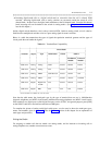
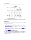
In figure 1-3, the protocols used at layer 1 and the DCE-created layer 2 are given. Layers 3 to 7 (and the
DTE-created layer 2) are embedded in the transmission stream and are meaningful only at the destination
DTE. Therefore, they are shown in the figure as "user defined," with no state changes until the transmission
stream reaches its destination.
__________________
* Not shown in the figure 1-3 is the treatment of D-channels in ISDN PRI and BRI transmissions. PRI and BRI D-channels transport
information elements that contain call-signaling and caller information. These information elements conform to ISDN level 3
protocol. In the case of BRI, the elements are created by the terminal or data module; for PRI, the elements are created by the
switch, which inserts them into the D-channel at the DS1 port. For ISDN transmissions, therefore, BRI terminals and data
modules, and DS1 ports insert, interpret, and strip both layer 2 DCE information and layer 3 information elements. Also, the DS1
port passes layer 3 information to the switch for processing.