


1-18 MULTIPLEXED COMMUNICATION
_ ___________________________________________________________________________________________________________________________
_ ___________________________________________________________________________________________________________________________
_ ___________________________________________________________________________________________________________________________
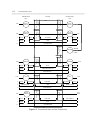
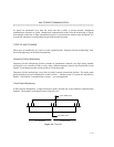
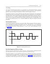
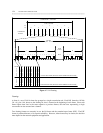
Time-division multiplexing can be bit interleaved or byte interleaved. With bit interleaving, the time slot
assigned to a particular channel is one bit long and the channel recurs every 15.5 microseconds over a DS1
link. With byte interleaving, the time slot is one byte long and recurs every 125 microseconds. (See figure
1-4.) For voice communication, each byte-interleaved time slot carries a byte representing a PCM-encoded
sample. For data communication, it carries the next sequential byte of information.
Byte-interleaved multiplexers are not compatible with bit-interleaved multiplexers.
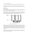
Statistical Multiplexing
Statistical multiplexers dynamically assign signals from incoming lines onto a single outgoing
communications path. This outgoing path is time-division multiplexed, but the time slots are assigned on
demand, making it possible for the number of incoming lines to be greater than the number of outgoing
time slots.
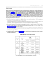
MULTIPLEXING OVER DS1 FACILITIES
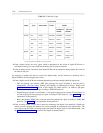
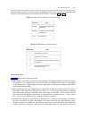
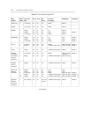
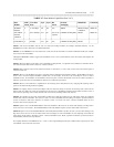
The hierarchy of digital transmission rates is given as "digital signal" (DS) numbers. DS numbers increase
from 0 to 4 as follows:
DS Number of
Number Speed DS0 Channels
_ ___________________________________________
DS0 64 kbps 1
DS1 1.544 Mbps 24
International DS1 2.048 Mbps 30
DS1C 3.152 Mbps 48
DS2 6.312 Mbps 96
DS3 44.736 Mbps 672
DS4 274.176 Mbps 4032
DS0 is the lowest rate and consists of a single 64-kbps digital channel. The DS0 data rate is achieved by
sampling the signal 8000 times a second and encoding each sample into an 8-bit byte. Above DS0, DS1 is
the first level at which multiplexing occurs and the higher levels represent the multiplexing of two or more
DS1 sources (plus additional overhead).
The System 75, System 85, and DEFINITY Generic 1 (G1) and Generic 2 (G2) communications systems
multiplex up to the DS1 level. In fact, DS1 facilities, like T1 trunks, are the medium through which many
time-division multiplexed signals are carried to and from the switch. Communication over these facilities
is managed through the DS1 port on the System 75, System 85, and DEFINITY G1 and G2 switches. How
line coding, framing, and signaling are performed over a particular T1 trunk depends upon how the DS1
port is administered, which, in turn, depends upon the types of equipment through which the signal travels
after it exits the switch. (For further clarification of the DS1 protocol, see DEFINITY Communications
System and System 75 and System 85 DS1/DMI/ISDN PRI Reference, 555-025-101.)