


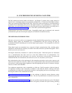
B. SYNCHRONIZATION OF DIGITAL FACILITIES
_ ______________________________________________________________________________________
_ ______________________________________________________________________________________
_ ______________________________________________________________________________________
The DS1 transmit and receive buffers (for Generic 1 and Generic 2) operate from a single external or
internal clock. Each digital switch can accommodate multiple DS1 or T1 spans that link multiple switches.
These may include both ISDN-PRI and DS1 links. Since each switch can transmit at a rate determined by
its internal clock, information will be lost if the digital network is not synchronized to a single clock.
Furthermore, one switch should be selected as the master and all others should obtain slave-timing from it.
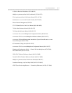
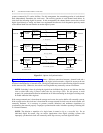
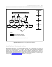
Figure B-1, Options for Synchronization, shows various DS1 synchronization applications.
Synchronization issues affect all network nodes. Compatibility details must be addressed, and a network
synchronization plan must be developed, deployed, and verified to be installed correctly.
THE NEED FOR SYNCHRONIZATION
The term synchronization refers to an arrangement whereby digital facilities operate from a common clock.
Whenever digital signals are transmitted over a communications link, the receiving end must be
synchronized with the transmitting end to read the digital signals properly. This arrangement is called link
synchronization.
When digital signals are transmitted over a network of digital communications links, switching nodes,
multiplexers, and transmission interfaces, all entities in this network must be synchronized together. This is
known as network synchronization.
With digital transmission, information is coded into discrete pulses. When these pulses are transmitted
over a communications link, there must be at least three different levels of synchronization. For
transmitting data, these levels are known as bit, character, and message synchronization. For pulse-code
modulation (PCM) voice transmission, the levels are bit, time-slot, and frame synchronization.
Bit synchronization refers to the requirement for the transmitter end and the receive end to operate at the
same clock rate so that bits are not lost. Other levels of synchronization refer to the need for the transmitter
and receiver to achieve proper phase alignment so that the beginning and the end of a character, message,
time slot, or frame can be identified.
For synchronous transmission, data is transmitted at a fixed rate. Each bit occupies a fixed-unit interval.
All significant transitions must correspond to multiples of the fixed-unit interval. Message and frame
synchronization are achieved by using special characters at the beginning and end of the message, and by
knowing the number of bits contained in each frame.
Figure B-1, Options for Synchronization, shows the exchange of digital bit streams between various
elements that require some form of synchronization. The role of synchronization is examined in each of the
three configurations.
Figure B-1-A, Options for Synchronization, shows one possible connection between a pair of D4-channel
banks. Such a connection (using D4-channel banks) can typically be found with a pair of analog switching
B-1