


1-10 TRANSMISSION STATES
_ ___________________________________________________________________________________________________________________________
_ ___________________________________________________________________________________________________________________________
_ ___________________________________________________________________________________________________________________________
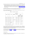
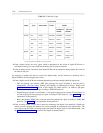
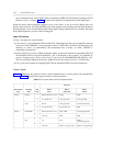
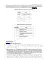
Table 1-2. Trunk Port Types
__________________________________________________________________
Circuit Packs
_ _________________________________________________________
Signal Type
DIMENSION S75/G1 S85/G2
_ _______________________
Traditional Universal
Module Module*
__________________________________________________________________
__________________________________________________________________
Analog CO LC08 TN747B SN230B TN747B
_ _________________________________________________________
Auxiliary LC13 TN763C SN231 TN763B
_ _________________________________________________________
DID LC09 TN753 SN232B TN753
_ _________________________________________________________
Tie LC11 TN760C SN233C TN760C
__________________________________________________________________
Digital DS1 N/A TN767 ANN11E TN767
_ _________________________________________________________
PRI N/A TN767 ANN35 TN767 and
TN555
__________________________________________________________________
* Universal modules are available only on the G2 switch.
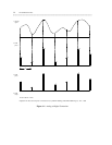
• From a digital switch, the voice signal, which is represented in the switch as digital PCM code, is
converted to analog via a codec built into the analog line or trunk circuit pack.
• From an analog switch, conversion of the internal PAM code to continuous analog signals also occurs at
the trunk or line port.
For outgoing or tandem calls that are routed over digital trunks, and for intercom or incoming calls to
digital terminals, the following processes occur:
• From a digital switch, PCM code treatment depends upon the port through which the signal exits.
— DS1 and primary rate interface (PRI) ports package the signal according to how the port is
administered. (The line coding, framing, and signaling are administrative choices. Refer to the
Multiplexed Communication section of this chapter for further details.) In addition, PRI ports
package their supervisory messages according to ISDN-PRI protocol.
— Digital-line ports (System 75 and Generic 1) and general-purpose ports (System 85 and Generic 2)
are both digital ports that package the signal according to DCP protocol. (See page 1-13 for an
explanation of this protocol.)
— Basic rate interface (BRI) ports are digital ports that package the signal according to ISDN BRI
protocol. (See page 1-13 for an explanation of this protocol.)
• From an analog switch, no provision is made for connecting with digital voice terminals. Outside the
switch, however, outgoing and tandem calls can be packaged for transmission over digital trunks. The
voice signal exits the switch via analog trunks, then enters the digital trunk at a D4 channel bank. (See
the Multiplexed Communication section of this chapter for further details.)