


TRANSMISSION STATES 1-15
_ ______________________________________________________________________________________
_ ______________________________________________________________________________________
_ ______________________________________________________________________________________
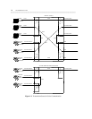
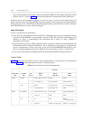
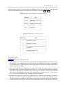
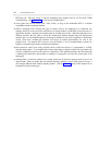
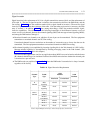
Note that both the physical-layer protocol and the DMI mode used in the connection are dependent upon
the type of 8-bit code used at layer 2 between the DTE and DCE. (See tables 1-4 and 1-5.)
Table 1-4. Physical-Layer Protocol vs. Character Code
_ _________________________________
Protocol Code
_ _________________________________
_ _________________________________
RS-232 Asynchronous 8-bit ASCII
Synchronous
_ _________________________________
RS-449 Asynchronous 8-bit ASCII
Synchronous
_ _________________________________
V.35 Synchronous
_ _________________________________
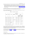
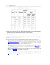
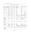
Table 1-5. DMI Mode vs. Character Code
_ _________________________________________________
DMI Mode Code
_ _________________________________________________
_ _________________________________________________
0 Synchronous (64 kbps)
_ _________________________________________________
1 Synchronous (56 kbps)
_ _________________________________________________
2 Asynchronous 8-bit ASCII (up to 19.2 kbps)
Synchronous
_ _________________________________________________
3 Asynchronous 8-bit ASCII
Private Proprietary
_ _________________________________________________
Connectivity Rules
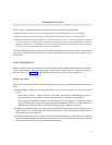
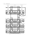
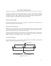
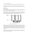
Figure 1-3 implies certain connectivity rules:
• In the figure, only the DS1 port and the analog trunk port are trunking facilities (all other ports shown
are line ports). For communication over these facilities, the destination DCE may be a hemisphere
away from the switch, and the signal may traverse any number of intervening switching systems before
reaching the destination DCE.
• Data originating at any type of digital device, whether DCP or BRI, can exit the switch at any type of
digital port — BRI, digital-line, GPP, PRI, DS1, and so on — as long as the call destination is equipped
with a data module using the same DMI mode as that used at the call origin. This is because, once the
data enters the switch through a digital port, its representation is uniform (raw bits — that is, digital
data — at layer 1, and DMI at level 2), regardless of where it originated.
• Although data entering the switch through an EIA port has not been processed through a data module,
the EIA port itself has a built-in data module. This means that inside the switch EIA-port data is
identical to digital-line or GPP data. Therefore, data entering the switch at a DCP-line port (digital-line
or GPP) can exit at an EIA port. Conversely, data entering the switch at an EIA port can exit at any