


PUBLIC AND PRIVATE DATA NETWORK CONNECTIONS 8-27
_ ______________________________________________________________________________________
_ ______________________________________________________________________________________
_ ______________________________________________________________________________________
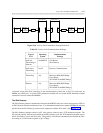
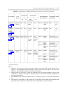
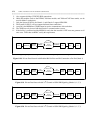
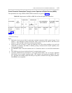
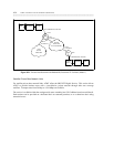
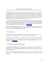
Table 8-7. Requirements for PBX-to-PBX Private Network T1.5 and T45 Connections
_ _______________________________________________________________________________________________
COMM TYPE TRUNK TYPE
FACILITIES CALL
_ _________________________________
RECOMMENDED NETWORK NOTES
SETUP DATA MODULE CHANNEL
S75 G1 S85 G2
(R2V3/V4)
_ _______________________________________________________________________________________________
_ _______________________________________________________________________________________________
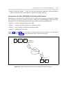
Robbed Bit Dedicated or Data Data TT†=109 TT=41 Mode 1 = MPDM/M1* AMI 1,2,3,
(see figure Dial-up (DMI) 7500B 8,10
8-17)
_ _______________________________________________________________________________________________
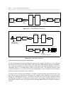
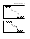
Robbed Bit Dedicated Data Data TT=109 TT=41 Mode 1 = MPDM/M1* AMI 1,2,3,
through (DMI) 7500B 4,10
D4/DSU
(see figure
8-18)
_ _______________________________________________________________________________________________
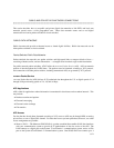
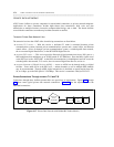
24th Channel Dedicated or Data or Data or V3=N/A TT=41 Mode 0 = MPDM Restricted or 1,5,8,
(see figure Dial-up AVD AVD V4: Signaling 7500B Unrestricted 9,10,11
8-19) TT=109 Type=20
(DMI) AVD
_ _______________________________________
Mode 1 = MPDM Restricted or 1,5,8,10
7500B Unrestricted
_ _______________________________________
Mode 2 = MPDM Restricted or 1,5,6,
7400A or B Unrestricted 8,10
7500B
_ _______________________________________________________________________________________________
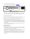
ISDN-PRI Dedicated or N/A Data or V3=N/A TT=40 Mode 0 = MPDM Restricted or 1,5,7
(see figure Dial-up AVD V4: Signaling Unrestricted 8,9,10
8-20) TT=109 Type=20
_ _______________________
(DMI) ISDN-PRI 7500B Unrestricted
_ _______________________________________
Mode 1 = MPDM Restricted or 1,5,6,7,
7500B Unrestricted 8,10
_ ________________________________
Mode 2 = MPDM Restricted or
7400A or B Unrestricted
7500B
_ _______________________________________________________________________________________________
† TT stands for trunk type.
Notes:
1. Dedicated circuits are provided via permanent switched connections (PSC) on the System 75 and
Generic 1; and dedicated switched connections (DSC) on the System 85 (R2V3 and R2V4) and
Generic 2. DSC amd PSC connections cannot be used together.
2. On the System 85 or Generic 2, trunk type DMI does not allow subnet trunking to be used with
AAR/ARS. In addition, with DMI, no modem pooling is allowed and the bearer capability class
must be set appropriately.
3. If an MPDM is used, it must be installed with a V.35 interface and an ACCUNET SW56 modification
kit.
4. The System 75 and Generic 1 PSC require that a SW56 DSU be used with the D4 channel bank.
System 85 (R2V4) and Generic 2 DSC allow either a SW56 DSU or a private line DSU.