


B-8 SYNCHRONIZATION OF DIGITAL FACILITIES
_ ___________________________________________________________________________________________________________________________
_ ___________________________________________________________________________________________________________________________
_ ___________________________________________________________________________________________________________________________
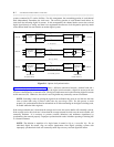
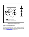
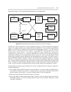
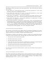
NOTE: These cables should not be installed if the switch is the master timing source
for the network.
BACKPLANE
CABLE TO
PRIMARY DS1
INTERFACE
(NOTE)
BACKPLANE
CABLE TO
SECONDARY DS1
INTERFACE
(NOTE)
OPTIONAL CROSS-COUPLED CABLE FROM DUPLICATED SCS
MAIN
PHASE
LOCKED
LOOP
MODULE
CONTROL
OR
TMS CLOCK
OSCILLATOR
SECONDARY
REFERENCE
PRIMARY
REFERENCE
STRATUM 4
HIGH ACCURACY
CLOCK
TN463 CIRCUIT PACK
Figure B-4. SCS (Generic 2)
Typically, the switch will be equipped with several DS1 circuit packs. The DS1 that is selected as the
primary or secondary reference is dependent on the internal cable configuration and administration details.
Here, each System 85 or Generic 2 that is configured with at least one DS1 requires a SCS, including the
master node. Unless synchronized to the network and not the stratum-3 or stratum-4 clock, the master node
will not have the primary and secondary synchronization cables.
A System 85 or Generic 2 may consist of either a single-module or multimodule architecture. Typically,
the switch architecture is unduplicated, but it may also be duplicated for critical reliability applications.
The switch architecture determines the equipment carriers that will contain the SCS circuit packs.
For single-module applications, the SCS is located in the module control carrier. In addition to the SCS, a
module clock is also required. The SCS controls the module clock. For multimodule applications, the SCS
is located in the time-multiplexed switch (TMS) carrier and controls the TMS clock oscillator.
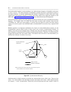
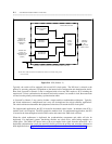
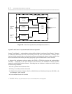
When the switch architecture is duplicated, the synchronization components and cables will also be
duplicated. For duplicated systems, functioning modules are called online, while backup modules are
called offline. The offline SCS phase locks to the cross-coupled clock signal from the online SCS. In a
duplicated synchronization system, the same DS1 facility provides the primary and secondary reference for
both duplicated halves. Figure B-5, Duplicated Synchronization Architecture and Cross Coupling, shows a