


SYNCHRONIZATION OF DIGITAL FACILITIES B-15
_ ______________________________________________________________________________________
_ ______________________________________________________________________________________
_ ______________________________________________________________________________________
and secondary references also apply to these references.
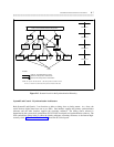
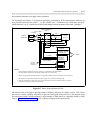
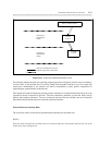
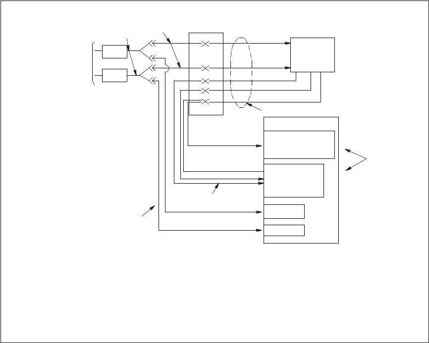
For System 85 and Generic 2, all functions previously performed by SCS synchronization software are
now provided external to the switch — by the external clock. Furthermore, the switch does not know
which reference (1 or 2) is online nor can the switch change from one reference to the other. phil/figb-7
NCTE
Y-CABLE
B25A CABLE
YELLOW
CROSS-CONNECT
FIELD
REF. 1
NOTE 2
NOTE 1
B25A CABLES
C6F OR
GR-380
CABLES
REF. 2
NOTE 3
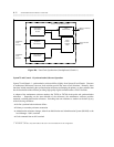
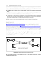
3. The TN492C or external alarm interface and TN2131 apply only to System\85 and Generic\02.
4. When the external clock is used, the SCS must not be administered. Those SCS software functions are done by
the hardware and firmware within the external clock.
1. The external clock cabinet has one 50-pin connector. It is labeled EXT CLOCK OUTPUT.
One B75A cable is required for connecting the cabinet to the cross-connect field.
2. Refer to the appropriate installation manual or wiring guide for details on how to configure the cross-connections.
NOTES:
CLOCK A
CLOCK B
ALARMS
DS1
DS1
ALARMS
SWITCH
TN492C OR
EXTERNAL ALARM
INTERFACE
TN2131
EXTERNAL-
CLOCK
INTERFACE
EXTERNAL
CLOCK
(NOTE 4)
PUBLIC
NETWORK
NCTE
Figure B-7. Public-Network External Clock
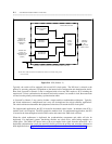
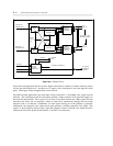
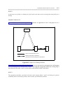
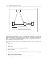
The external clock is designed to provide stratum-3 reliability and exists in a duplex version. This version
provides hot standby capability (the ability to pull out circuit packs with power on) to the alternate clock
and may be used with a switch containing a single module or TMS control or a duplicate module or TMS
control. Figure B-8, External Clock, shows a functional diagram of the external clock.