


Page 16
724-746-5500 | blackbox.com
Chapter 1: Specifications
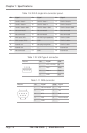
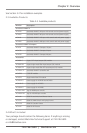
Table 1-9. DVI-D single-link connector pinout.
Pin Signal Pin Signal Pin Signal
1 T.M.D.S. data 2- 9 T.M.D.S. data 1- 17 T.M.D.S. data 0-
2 T.M.D.S. data 2+ 10 T.M.D.S. data 1+ 18 T.M.D.S. data 0+
3 T.M.D.S. data 2 GND 11 T.M.D.S. data 1 GND 19 T.M.D.S. data 0 GND
4 Not connnected 12 Not connected 20 Not connected
5 Not connected 13 Not connected 21 Not connected
6 DDC input (SCL) 14 +5 VDC high impedance 22 T.M.D.S. GND
7 DDC output (SDA) 15 GND 23 T.M.D.S. clock+
8 Internal use 16 Hot plug recognition 24 T.M.D.S. clock-
C1 Internal use — — C3 Internal use
C2 Not connected C5 GND C4 Internal use
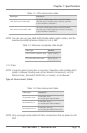
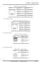
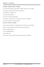
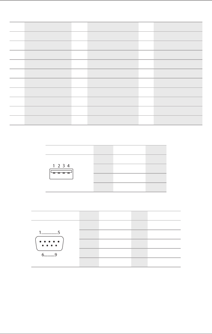
Table 1-10. USB Type A connector.
Picture Pin Signal Color
1 VCC (+5 VDC) Red
2 Data - White
3 Data + Green
4 GND Black
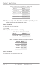
Table 1-11. DB9 connector.
Picture Pin Signal Color Signal
1 Not connected 6 DTR
2 CTS 7 TxD
3 RTS 8 RxD
4 DSR 9 Not connected
5 GND — —