


Confidential
5-49
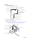
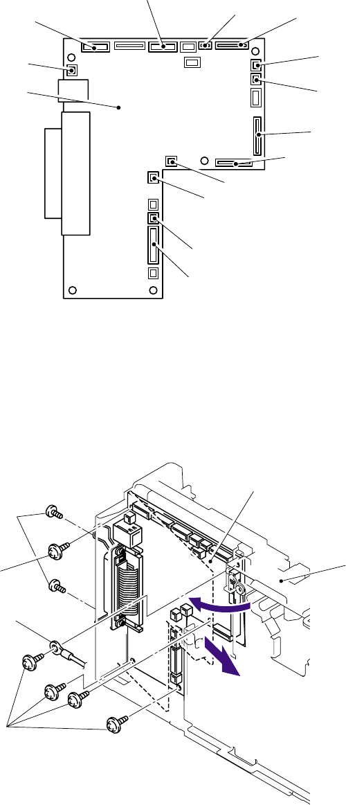
5.1.19 Main PCB
< DCP7010/7020/7025, MFC7420 >
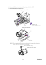
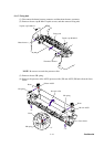
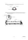
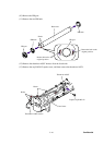
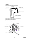
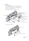
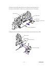
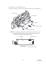
(1) Disconnect the thirteen connectors from the main PCB.
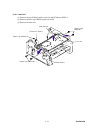
(2) Remove the five cup S M3x6 taptite screws and FG harness ASSY 6.
(3) Remove the two flat S M3x8 taptite screws.
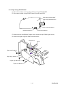
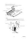
(4) Remove the main PCB from main frame L.
NOTE: When replacing the main PCB, refer to ‘ADJUSTMENTS AND UPDATING OF
SETTINGS, REQUIRED AFTER PARTS REPLACEMENT’ in Chapter 6.
Main PCB
Taptite flat S M3x8
Taptite cup S M3x6
Taptite cup S M3x6
FG harness ASSY 6
Main frame L
1
2
HVPS connecto
r
(It has been taken back.)
Polygon motor connecto
r
(LV harness ASSY)
N
ew toner sensor connecto
r
LD harness 5P
connector
Main PCB
Speaker connecto
r
N
CU connecto
r
Cover sensor connecto
r
LVPS connecto
r
Fan motor 60 unit connecto
r
Thermistor relay harness
Main motor connecto
r
Battery connecto
r
Control panel connecto
r