


Confidential
CHAPTER 8 MAINTENANCE MODE
This chapter describes the maintenance mode which is exclusively designed for the purpose of
checks, settings and adjustments using the keys on the control panel.
You can customize the EEPROM according to the shipment destination of the machine
concerned. In addition, you can perform operational checks of the LCD, control panel PCB or
sensors, perform a print test, display the log information or error codes, and modify firmware
switches (WSW).
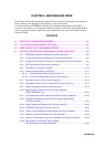
CONTENTS
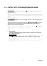
8.1 ENTRY INTO THE MAINTENANCE MODE ...................................................................8-1
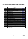
8.2 LIST OF MAINTENANCE-MODE FUNCTIONS ............................................................. 8-2
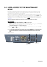
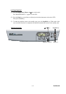
8.3 USER-ACCESS TO THE MAINTENANCE MODE.........................................................8-3
8.4 DETAILED DESCRIPTION OF MAINTENANCE-MODE FUNCTIONS ......................... 8-5
8.4.1 EEPROM Parameter Initialization (Function code 01/91) ................................... 8-5
8.4.2 Printout of Scanning Compensation Data (Function code 05)............................8-6
8.4.3 Placement of CIS Unit in Position for Transportation (Function mode 06).......... 8-8
8.4.4 ADF Performance Test (Function mode 08) .......................................................8-9
8.4.5 Test Pattern 1 (Function mode 09).................................................................... 8-10
8.4.6 Firmware Switch Setting and Printout ...............................................................8-11
8.4.6.1 Firmware switch setting (Function mode 10) ............................................ 8-11
8.4.6.2 Printout of firmware switch data (Function mode 11)................................ 8-14
8.4.7 Operation Check of LCD (Function mode 12)................................................... 8-16
8.4.8 Operational Check of Control Panel PCB (Function mode 13).........................8-17
8.4.9 Sensor Operational Check (Function mode 32)................................................8-18
8.4.10 Received Data Transfer Function (Function mode 53)
(MFC7420/7820N only) ....................................................................................8-20
8.4.11 Fine Adjustment of Scan Start/End Positions (Function mode 54) ................... 8-22
8.4.12 Acquisition of White Level Data and CIS Scanner Area Setting
(Function mode 55) ...........................................................................................8-24
8.4.13 Paper Feeding and Ejecting Test (Function mode 67)...................................... 8-24
8.4.14 EEPROM Customizing (Function mode 74)...................................................... 8-25
8.4.15 Display of the Equipment’s Log Information (Function mode 80) ..................... 8-26
8.4.16 Machine Error Code Indication (Function mode 82).......................................... 8-28
8.4.17 Output of Transmission Log to the Telephone Line (Function mode 87).......... 8-28
8.4.18 Cancellation of the Memory Security Mode
(Not applicable to the Japanese model)............................................................ 8-29