


Chapter 3: Installation
3-10 2H23-50R/2H33-37R User’s Guide
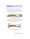
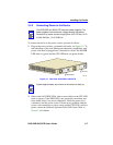
4. Verify that a link exists on each twisted pair segment of the RJ21
connector by checking that the port Link LEDs above the connector
are on (flashing amber, blinking green, or solid green). If any of the
Link LEDs are off, perform the following steps to check the associated
twisted pair segments. The problem is resolved when the Link LED
comes on.
a. Verify that the device at the other end of the twisted pair segment
is on and connected to the segment.
b. Verify that the RJ21 connector associated with the twisted pair
segment has the proper pinouts and check the cable for continuity.
c. Check that the twisted pair connection meets the dB loss and cable
specifications outlined in Chapter 2.
If a link is not established, contact the Cabletron Systems Global Call
Center. Refer to Section 1.6 for details.
5. Repeat steps 1 through 5 above, until all connections have been made.
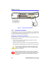
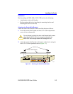
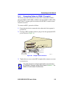
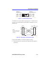
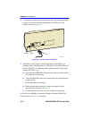
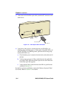
3.5.2 Connecting a UTP Segment to the FE-100TX
An FE-100TX installed in slot 5 and/or 6 of a 2H23-50R has an internal
crossover switch. When connecting a workstation, use a straight-through
cable and set the Fast Ethernet Interface Module crossover switch shown
in Figure 3-7 to the crossed over position marked with X. When
connecting networking devices, such as another bridge, repeater, or
router, use a straight-through cable and set the Fast Ethernet Interface
Module crossover switch shown in Figure 3-7 to the straight-through
position (not crossed over), marked with =.
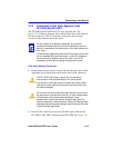
NOTE
To ensure proper operation, use only Category 5 Unshielded
Twisted Pair (UTP) cabling that has an impedance between 85
and 111 ohms.