


Connecting to the Network
2H23-50R/2H33-37R User’s Guide 3-11
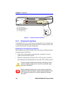
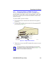
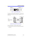
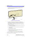
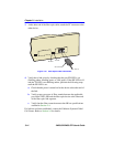
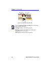
Figure 3-7 FE-100TX Crossover Switch
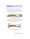
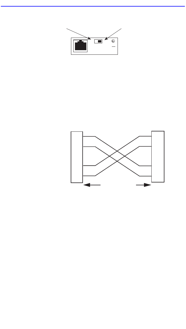
A schematic of a crossover cable is shown in Figure 3-8. If the wires do
not cross over, use the switch on the FE-100TX to internally cross over
the RJ45 port.
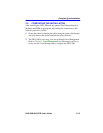
Figure 3-8 Cable Pinouts - RJ45 Crossover Cable
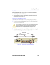
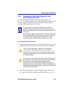
Connect an FE-100TX to a twisted pair segment as follows:
1. Ensure that the device connected to the other end of the segment is
powered on.
Position X
(crossed over)
1. RX+
2. RX-
3. TX+
4. NC
5. NC
6. TX-
7. NC
8. NC
Position =
(not crossed over)
1. TX+
2. TX-
3. RX+
4. NC
5. NC
6. RX-
7. NC
8. NC
FE-100TX
10
16651_05
100
=
x
TX+
TX–
RX+
RX– 2
1
3
6
TO
10BASE-T Device Port
TX+
TX–
2
1
3
6
NOTE:
RX+/RX– and TX+/TX–
must share a common
color pair.
TO
RJ45 Port
2251-31
RJ45 to RJ45
RX+
RX–