


Chapter 5: Local Management
5-38 2H23-50R/2H33-37R User’s Guide
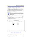
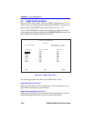
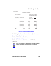
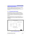
5.10 SWITCH CONFIGURATION SCREEN
The Switch Configuration screen, Figure 5-17, provides the basic setup
options to make a switch operational in your network.
To access the Switch Configuration screen from the Device Configuration
Menu screen, use the arrow keys to highlight the SWITCH
CONFIGURATION menu item and press ENTER. The Switch
Configuration screen displays up to 8 ports. To view or edit the fields for
other ports, highlight NEXT at the bottom of the screen and press
ENTER.
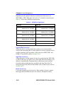
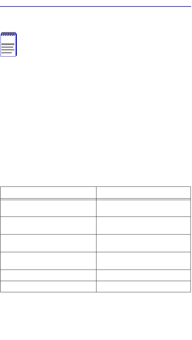
Depending on the optional interfaces installed and if the device is a
2H23-50R or 2H33-37R, there can be 10 or 7 ports, respectively. As
shown in Table 5-4, there are two network ports per RJ21 CONN
connector.
NOTE
The Switch Configuration screen is not available if the
operational mode of the device is set to SECURE FAST VLAN.
This screen may only be used when the device is configured to
operate as an 802.1D or 802.1Q switch.
Table 5-4 CONN/Port Organization
2H23-50R 2H33-37R
CONN 1 = Network Port 1, 10 Mbps
Network Port 2, 100 Mbps
CONN 1 = Network Port 1, 10 Mbps
Network Port 2, 100 Mbps
CONN 2 = Network Port 3, 10 Mbps
Network Port 4, 100 Mbps
CONN 2 = Network Port 3, 10 Mbps
Network Port 4, 100 Mbps
CONN 3 = Network Port 5, 10 Mbps
Network Port 6, 100 Mbps
CONN 3 = Network Port 5, 10 Mbps
Network Port 6, 100 Mbps
CONN 4 = Network Port 7, 10 Mbps
Network Port 8, 100 Mbps
HSIM = Port 7
Fast Ethernet Slot 5 = Port 9
Fast Ethernet Slot 6 = Port 10