


INSTALLATION
3-9
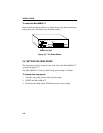
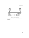
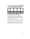
RJ45 Plug to RJ45 Plug
(at TCU) (at device port)
Pin 3 (Receive -) . . . . . . . . . to. . . . Pin 3 (Transmit -)
Pin 4 (Transmit +) . . . . . . . . to. . . . Pin 4 (Receive +)
Pin 5 (Transmit -). . . . . . . . . to. . . . Pin 5 (Receive -)
Pin 6 (Receive +) . . . . . . . . . to. . . . Pin 6 (Transmit +)
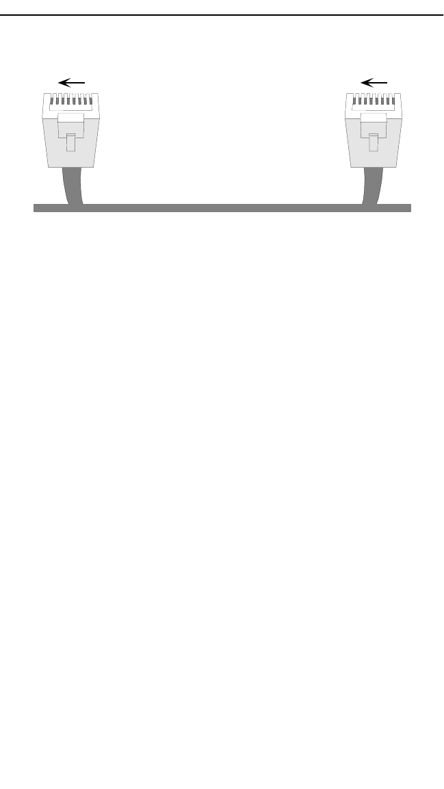
Figure 3-9. Network lobe pinouts
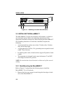
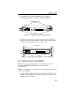
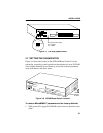
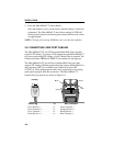
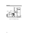
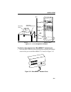
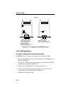
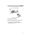
Figure 3-10 and Figure 3-11 illustrate possible MicroMMAC-T cabling
configurations.
18
RJ45 Plug
18
RJ45 Plug