


5-1
CHAPTER 5
TROUBLESHOOTING
This chapter describes and explains how to use LANVIEW LEDs and the
Liquid Crystal Display (LCD) to troubleshoot physical layer network
problems. The chapter concludes with an overview of the POWER UP
Diagnostic Test.
5.1 USING LANVIEW LEDs
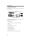
LANVIEW LEDs (located on the front panel) are Cabletron Systems’
built-in visual diagnostic and status monitoring system. Use the LEDs to
monitor network status or diagnose physical-layer network problems.
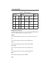
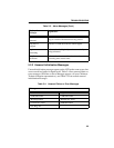
Table 5-1 below lists and describes front panel LEDs.
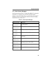
Table 5-1. LANVIEW LEDS
LED NAME LED COLOR DEFINITION
Lobe Port Status
(Ports 1-24)
Off
Green
Red
Red (blinking)
No Link/Port Enabled
Link/Port Enabled
No Link/Port Disabled
Link or Ring Speed Fault/Port Disabled
16Mb/s
(Ring Speed)
Yellow
Off
16MbpsRing Speed
4 Mbps Ring Speed
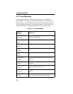
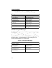
ACT
(Network Activity)
Green (Flashing)
Red (Flashing)
Off
Good Frames
Beacon Recovery Running
No Activity
MGMT
(Network Management)
Green
Red
Management Agent Active
Management Agent Not Active
CPU
(Central Processing Unit)
Off
Green (Flashing)
Green (Blinking)
Red
Yellow
Yellow/Green
No Power
CPU Initializing
CPU Functioning (normal)
CPU Not Functioning
Diagnostic Testing
Booting
NOTE: “Flashing” indicates an irregular LED pulse. “Blinking”
indicates a steady LED pulse.