


148 Appendix E: Understanding IP and IP addressing
297-8991-910 Standard 03.01 August 1999
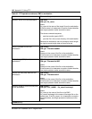
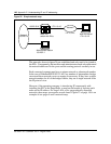
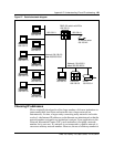
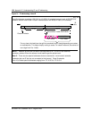
Figure 26 Simple network map
The networks shown in figure 26 are established and only need to be joined to
the EIUs. Consequently, the installers and administrators need only understand
the network addresses for the ports and the routing protocol currently in use.
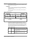
Each connected segment must have a unique network or subnetwork number.
In the case of Ethernet/IEEE 802.3 LAN, any number of intermediate bridges
can extend these networks across a campus as necessary. If they have a single
network number for all of the bridged cables, they are a single network from
the IP point of view.
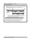
However, if the operating company is introducing IP concurrently with
installing the EIU in the SuperNode, a map has the benefit of showing each
node and its IP address. For large LANs or for geographically dispersed
networks, these maps can require several sheets. Figure 27 on page 149 is an
example of one page of such a network map.
Network
DMS-100
switch with EIUs
172.113.4.5133.25.30.8
172.113.4.0
Main file server
172.113.4.2
Network
Administrator station
133.25.2.1
133.25.0.0