


32 Chapter 1: Introduction to the EIU
297-8991-910 Standard 03.01 August 1999
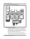
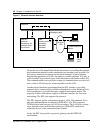
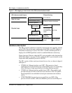
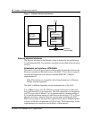
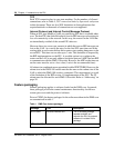
Figure 8 Ethernet interface architecture
Ethernet physical interfaces
The physical interface to the Ethernet system is defined by the paddle board
located behind the EIC. The interfaces available are described in the following
sections.
Attachment unit interface—NT9X85AA
This card is a 15-pin D-type connector that provides the interface between the
Ethernet controller and the media access unit (MAU). This is the most generic
interface and supported as an industry standard (IEEE 802.3 10Base5
implementation).
Note: This interface is compatible with all implementations of Ethernet
through external equipment.
The MAU is different depending on the implementation of the LAN.
For a 10Base5 coax LAN, the MAU has coaxial connections on either side
using field installed N-type connectors. The AUI connection is on an adjacent
side. The coax cable is about 0.5 in. in diameter and has a bending radius of
0.5 m and the minimum amount of cable between transceivers is 2.5 m. These
physical restrictions must be taken into account when installing the MAU.
MAUs have a range of 500 m per bus segment which may be bridged together
to form a LAN that is a maximum of 2500 m long. The disadvantages of this
implementation are installation and difficulty of maintenance.
P-bus
LPP
MAU
NTEX22
CPU/IPF
Ethernet
Ethernet
memory
controller
Ethernet
controller
Multiport
buffer memory
Ethernet
coaxial cable