


Chapter 1: Introduction to the EIU 25
DMS-100 Family EIU User Guide TELECOM12
second-level message switches are referred to as local message switches
(LMS).
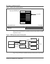
The frame transport bus (F-bus) is a 32-Mbit/s messaging bus that resembles
the MS in its protocol. The use of a narrower data path allows access to two
buses through a single backplane. This feature lets a single processor card
connect to both planes of the LMS and to survive faults on one plane. Links
interconnecting planes of the LMSs are provided to allow transparent message
rerouting in the case of single faults.
Note: Because the interconnecting F-bus is a wire bus, it is limited to a
single cabinet.
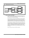
Inter-message switch links required with LPP
Inter-message switch links (IML) between the MS planes are also required to
improve robustness. For example, two peripherals (such as an applications
processor and an EIU) can lose communication with each other if they
message through different planes of the MS. In this scenario, assume that one
peripheral is messaging through plane 0 only because of a failure. If the second
peripheral loses its link to plane 0, the two peripherals cannot communicate
even though they can communicate to the DMS-core for maintenance
purposes.
For this reason, there is a pair of IMLs in integrated service node (ISN)
switches. These IMLs are DS512 links that operate at 1024 Kbit/s. Other
improvements to the MS hardware are also required to conform with the ISN
maintenance strategies.
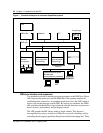
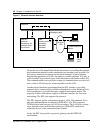
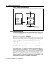
Data communications interface architecture
The overall architecture of the data communications subsystem is based
partially on the premise that the processing and the access method for these
entities must be separate.
For this reason, application processors (AP) have the intelligence to drive the
link protocols. This arrangement allows freedom to change access methods
and allows flexibility in satisfying the processing requirements for each
protocol. The emphasis is on providing locally attached, nonswitched
connections primarily for OAM interfaces. An example of the overall data
flow for the data communications environment is shown in figure 2.