


182 Appendix H: ASU background information
297-8991-910 Standard 03.01 August 1999
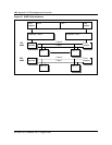
DMS-bus. While the rate adapter is responsible for mediating traffic flow
between the F-bus and T-bus, the T-bus provides the following functionality:
• T-bus for inter- and intra-LPP messaging (inter-LPP messaging is carried
on DS30 links)
• access to mapper hardware for logical-to-physical addressing
• supports the LMS central processing unit (CPU), which is responsible for
LPP diagnostics, maintenance, and maintaining configuration specific data
in its memory
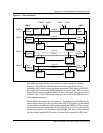
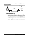
Single-shelf link peripheral processor
The SSLPP is a cost-competitive alternative for offices that do not need the
number of slots offered by the LPP. The operating company can provision a
maximum of 12 ASUs on the SSLPP.
The SSLPP allows the F-bus from a single link interface shelf (LIS) to connect
directly to the DMS-bus with a fiber optic cable. The functions of the LMS are
assumed by the DMS-bus. The shelf assembly is identical to that used in the
LPP, with the major difference being the method used to connect it to the
message switch (MS).
In the SSLPP, the F-bus interface circuit pack is replaced with an F-bus
controller circuit pack, which handles the messaging to and from the ASUs and
services and provides shelf control. The F-bus extender paddle board is
replaced with a fiber interface paddle board, which interfaces to the fiber optic
link and provides the system clock and out-of-band reset reception. Each F-bus
controller connects to one of the two F-buses for the shelf and provides a
connection to an MS. This arrangement provides the same minimum level of
redundancy as in the LPP (where each F-bus is connected to only one of the
two LMSs). In a single office, a maximum of two SSLPPs can be connected to
the MS. The fiberized interface allows a selectable number of channels for
future requirements (128 and 256 channels).
Figure 45 on page 183 provides an overview of the SSLPP configuration.