


Appendix H: ASU background information 181
DMS-100 Family EIU User Guide TELECOM12
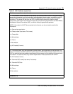
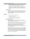
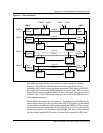
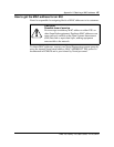
Figure 44 LPP architecture
The LMS represents the first level of the two-level message switching
hierarchy. The LMS provides the interface between the F-bus seen by
individual ASUs and services and non-channelized DS30 links to the DMS-
bus. The LMS is duplicated: LMS0 interfaces to F-bus0 and LMS1 to F-bus1.
Each ASU has access to either F-bus0 or F-bus1. Messages are sent or received
on either F-bus. Each LMS plane connects to each side of the DMS-bus in a
fully redundant manner.
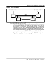
Each LMS plane consists of a maximum of 13 circuit packs and paddle boards,
and occupies one-half of the top shelf of the LPP. The majority of the printed
circuit boards are identical to those employed in the DMS-bus. These circuit
packs constitute the transport bus (T-bus). The T-bus is a 32-bit-wide parallel
bus that also operates at a clock rate of 4.096 MHz. The T-bus resides between
the rate adapter and the DS30 interface circuits that connect the LPP to the
Shelf 2
2 MS 12 MS 0
Shelf 1
2 DS30
Rate
adapter
LMS 0
Shelf 0 T-bus DS30
F-bus
repeater
ASU 0
F-bus 0
F-bus 1
F-bus
repeater
ASU 11
Rate
adapter
T-busDS30
LMS 1
2 MS 12 MS 0
F-bus
repeater
ASU 12
F-bus 0
F-bus 1
F-bus
repeater
ASU 23
Shelf 3
F-bus
repeater
ASU 24
F-bus 0
F-bus 1
F-bus
repeater
ASU 35