


Chapter 3: Installation Requirements and Specifications
3-2 SEHI User’s Guide
3.1.1 HubSTACK Interconnect Cable Requirements
Attach the SEHI to modules in the stack with the SEHI HubSTACK
Interconnect cable available only from Cabletron Systems. Refer to
Chapter 1 for cable part numbers. The cable attaches to the SEHI rear
panel bus port.
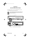
The rear panel of the SEHI has an Interconnect Bus Out port (male
connector) to stack SEH non-intelligent hubs together. Stack up to four
SEH hubs together with one SEHI.
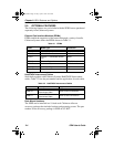
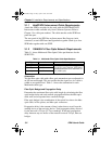
3.1.2 10BASE-FL Fiber Optic Network Requirements
Table 3-1 shows Multimode Fiber Optic Cable specifications for the
SEHI-22FL.
Attenuation
Test the fiber optic cable with a fiber optic attenuation test set adjusted for
an 850 nm wavelength. This test verifies that the signal loss in a cable is
within an acceptable level. Table 3-1 shows the attenuation for each
Multimode cable type.
Fiber Optic Budget and Propagation Delay
Determine the maximum fiber optic cable length by calculating the fiber
optic budget delay and total network propagation before the fiber optic
cable runs are incorporated into a network design.
Fiber optic budget is the combination of the optical loss due to the fiber
optic cable, in-line splices, and fiber optic connectors.
Propagation delay is the amount of time it takes data to travel from the
sending device to the receiving device. Total propagation delay allowed
for the network is 25.6 µs (51.2 µs roundtrip). If the total propagation
delay between any two nodes on the network exceeds 25.6 µs, then use
bridges.
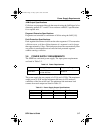
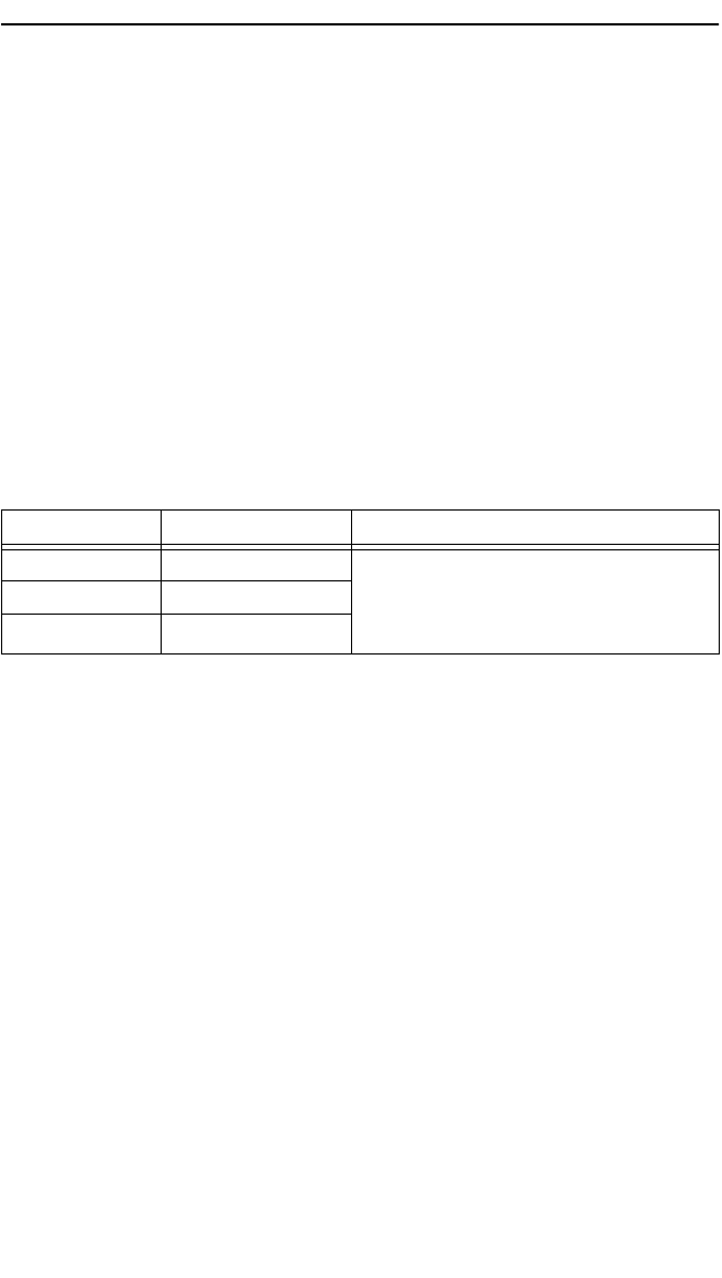
Table 3-1 Multimode Fiber Optic Cable Specifications
Cable Type Attenuation Maximum Cable Length
50/125 µm 13.0 dB or less Maximum fiber optic cable length is 2
km (2187.2 yds). However, IEEE 802.3
specifications allow for a maximum of 1
km (1093.6 yds).
62.5/125 µm 16.0 dB or less
100/140 µm 19.0 dB or less
SEHI Book Page 2 Friday, April 19, 1996 10:46 AM