


SEHI User’s Guide 5-1
CHAPTER 5
CONNECTING TO THE NETWORK
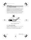
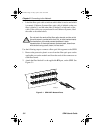
This chapter outlines the procedure for connecting the SEHI to a network.
Ensure that the network meets the guidelines and requirements outlined in
Chapter 3, Installation Requirements and Specifications, before
installing the SEHI.
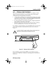
5.1 CONNECTING THE SEHI TO THE NETWORK
The procedure for connecting network segments to the SEHI varies
depending on the media and ports being connected. Refer to the following
list and perform the procedure described in the subsections that apply to
connecting the SEHI to a network:
• Connecting Network Ports Section 5.1.1
• Connecting a UTP segment to an EPIM-T Section 5.1.2
• Connecting a fiber segment to an EPIM-F1/F2/F3 Section 5.1.3
• Connecting a Thin Coaxial Segment to an EPIM-C Section 5.1.4
• Connecting an AUI cable to an EPIM-A Section 5.1.5
• Connecting an AUI Cable to an EPIM-X Section 5.1.6
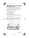
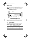
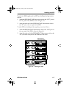
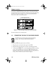
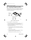
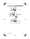
5.1.1 Connecting Network Ports
The SEHI-22FL has ST style network ports. Read the following
guidelines before connecting a fiber optic link segment to the SEHI:
• Insert the connector into the port with the alignment key on the
connector inserted into the alignment slot on the port. The connector
is then turned clockwise to lock it down.
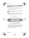
• The physical communication link consists of two strands of fiber optic
cabling: the Transmit (TX) and the Receive (RX). Connect the TX
strand from the applicable port on the module to the receive port of a
fiber optic Ethernet device at the other end of the segment. The RX
strand of the applicable port on the module connects to the transmit
port of the fiber optic Ethernet device.
SEHI Book Page 1 Friday, April 19, 1996 10:46 AM