


EPIM Specifications
SEHI User’s Guide A-3
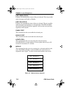
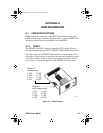
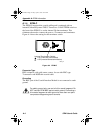
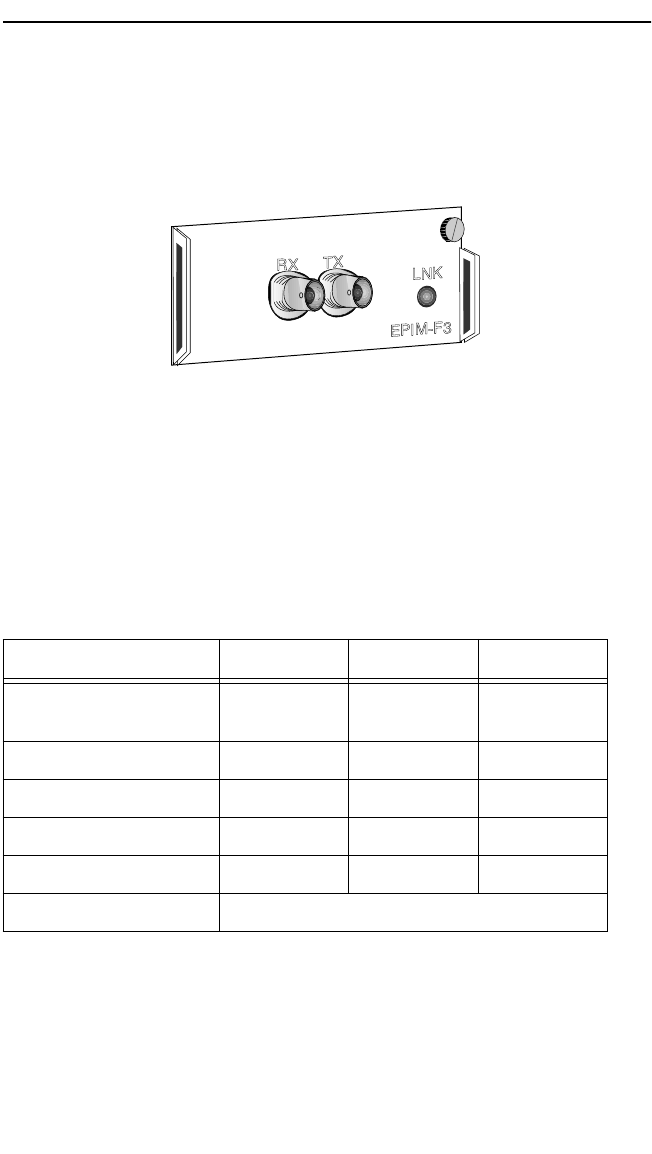
A.1.3 EPIM-F3
The EPIM-F3 (Figure A-3) supports Single Mode Fiber Optic cabling. It
has an internal Cabletron Systems FOT-F Fiber Optic Transceiver and is
equipped with ST Connectors. EPIM-F3 specifications are listed below.
Figure A-3 EPIM-F3
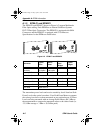
Transmitter Power decreases as temperatures rise and increases as
temperatures fall. Use the Output Power Coefficient to calculate increased
or decreased power output for the operating environment. For example,
the typical power output at 25°C is -16.4 dBm. For a 4°C temperature
increase, multiply the typical coefficient (-0.15 dBm) by four and add the
result to typical output power (4 x -0.15 dBm + -16.4 = -17.0).
The transmitter power levels given above are Peak Power Levels after
optical overshoot. Use a Peak Power Meter to compare the values given
above to those measured on any particular port. If you are using an
Average Power Meter, add 3 dBm to the measurement to compare the
average power values to the values listed above
(i.e., -33.5 dBm average + 3 dBm = -30.5 dBm peak).
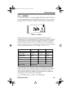
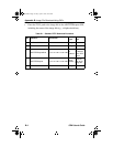
Parameter Typical Minimum Maximum
Transmitter Peak
Wave Length 1300 nm 1270 nm 1330 nm
Spectral Width 60 nm - 100 nm
Rise Time 3.0 ns 2.7 ns 5.0 ns
Fall Time 2.5 ns 2.2 ns 5.0 ns
Duty Cycle 50.1% 49.6% 50.7%
Bit Error Rate Better than 10
-10
1490_32
SEHI Book Page 3 Friday, April 19, 1996 10:46 AM