


2-7
Cisco 10000 Series Router SIP and SPA Hardware Installation Guide
OL-13838-03
Chapter 2 Cisco 10000 Series Router SPA Interface Processor-600
Cisco 10000 SIP-600 Overview
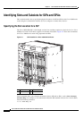
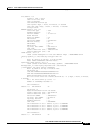
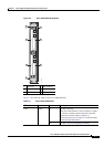
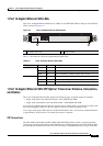
Figure 2-2 Cisco 10000 SIP-600 Faceplate
Table 2-3 describes the LED on the Cisco 10000 SIP-600.
.
1 Fail LED 4 SPA subslot 2
2 SPA subslot 0 5 SPA subslot 3
3 SPA subslot 1 6 Ejector levers
210610
0
1
SPA INTERFACE PROCESSOR
10000-SIP-600
FAIL
2
3
CISCO
10000
6
6
1
A
/
L
A
/
L
S
T
A
T
U
S
SPA-24XDS-SFP
0
1
A
/
L
A
/
L
S
T
A
T
U
S
SPA-24XDS-SFP
0
1
5
4
2
3
Table 2-3 Cisco 10000 SIP-600 LED
LED Label Color State Meaning
FAIL Amber On The SIP is booting.
If the Fail LED remains on for more than 5 seconds
or if it turns on during normal operation, the SIP
experienced a failure. Refer to
Chapter 7,
“Troubleshooting the Installation” for SIP and SPA
troubleshooting information.
Off The SIP is active and operating normally.