


3-3
Cisco 10000 Series Router SIP and SPA Hardware Installation Guide
OL-13838-03
Chapter 3 Cisco 10000 Series Router Shared Port Adapters
Bandwidth Oversubscription
SIP Ingress Oversubscription
The Application-Specific Integrated Circuit (ASIC) device for the Cisco 10000 SIP-600 can receive over
40 Gbps of ingress data from the four SPA SPI4.2 interfaces. While the ASIC supports 40 Gbps of
ingress memory write bandwidth, the ingress memory read bandwidth on the SIP is the 10 Gbps rate of
the SPI4.2 interface to the backplane.
To support this four-to-one oversubscription, the SIP has 128 MB of error correction code (ECC)
protected buffering that is divided between the four SPA subslots. The ingress buffering absorbs transient
bursts of traffic from the SPAs.
Each Ethernet SPA has a pair of ingress queues (high and low priority) for each physical port. Each pair
of queues is configured into the ingress scheduler based on the bandwidth capability of the port. For
example, a 10GE interface is allocated 10 times the bandwidth of a single GE interface. The ingress
scheduler will round robin amongst each pair of queues attempting to provide the minimum configured
bandwidth.
Within each pair of ingress queues, traffic from the high priority queue is serviced before the normal
priority queue. Traffic is selected into a high priority ingress queue by means of the plim qos commands
as described in the Cisco 10000 Series Router SIP and SPA Software Configuration Guide.
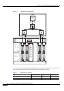
PRE4 Egress Oversubscription
When operating with a PRE4, each SIP is viewed as one line card. When there is packet oversubscription
on the PRE4, multiple egress queues may contain packets waiting to be transmitted to the SIP. For
example, a SIP on the left side of the chassis contains a 1-Port 10-Gigabit Ethernet SPA and a 5-Port
Gigabit Ethernet SPA. On the right side of the chassis, the same SPAs are in separate SIPs. In this
scenario, the combined egress bandwidth on the right side of the chassis may exceed the egress
bandwidth on the left side.
In an oversubscribed system, we recommend that you balance the overall traffic bandwidth between the
left and right sides of the chassis. For example, balancing subscriber traffic on one side and trunk traffic
on the other side.
Note Install the SIPs into the slots that are at the extreme ends of the chassis first.
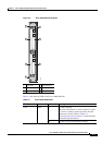
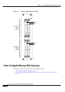
SIP Performance with a PRE3
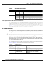
When operating with a PRE3, each SIP is viewed as two separate, full-slot line cards, each with a 2.8
Gbps interface, as shown in
Figure 3-2. A pair of SPA subslots are assigned to one of the backplane
interfaces on the SIP. If one SPA pair does not fully utilize its respective 2.8 Gbps backplane bandwidth,
the other SPA pair may not use the excess bandwidth. When using a SIP with a PRE3, we recommend
that you balance the overall SPA bandwidth between the top two SPA subslots and the bottom two SPA
subslots. Also, install the SIPs in the outside slots of the chassis first.
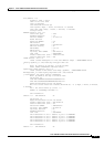
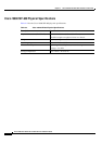
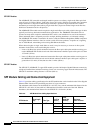
5-Port Gigabit Ethernet SPA 1 Gbps 5 5 Gbps
8-Port Gigabit Ethernet SPA 1 Gbps 8 8 Gbps
Table 3-1 SPA Bandwidth Capacity
SPA Per-Port Bandwidth Number of Ports Total Bandwidth