


10-3
Catalyst 3550 Multilayer Switch Software Configuration Guide
78-11194-03
Chapter 10 Configuring STP
Understanding Basic STP Features
Multiple active paths among end stations cause loops in the network. If a loop exists in the network, end
stations might receive duplicate messages. Switches might also learn end-station MAC addresses on
multiple Layer 2 interfaces. These conditions result in an unstable network.
STP defines a tree with a root switch and a loop-free path from the root to all switches in the Layer 2
network. STP forces redundant data paths into a standby (blocked) state. If a network segment in the
spanning tree fails and a redundant path exists, the spanning-tree algorithm recalculates the
spanning-tree topology and activates the standby path.
When two interfaces on a switch are part of a loop, the STP port priority and path cost settings determine
which interface is put in the forwarding state and which is put in the blocking state. The STP port priority
value represents the location of an interface in the network topology and how well it is located to pass
traffic. The STP path cost value represents media speed.
Bridge ID, Switch Priority, and Extended System ID
The IEEE 802.1D standard requires that each switch has an unique bridge identifier (bridge ID), which
determines the selection of the root switch. Because each VLAN is considered as a different logical
bridge with PVST+, the same switch must have as many different bridge IDs as VLANs configured on
it. Each VLAN on the switch has a unique 8-byte bridge ID; the two most-significant bytes are used for
the switch priority, and the remaining six bytes are derived from the switch MAC address.
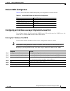
In Release 12.1(8)EA1 and later, Catalyst 3550 switches support the 802.1T spanning-tree extensions,
and some of the bits previously used for the switch priority are now used as the VLAN identifier. The
result is that fewer MAC addresses are reserved for the switch, and a larger range of VLAN IDs can be
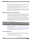
supported, all while maintaining the uniqueness of the bridge ID. As shown in Table 10-1, the two bytes
previously used for the switch priority are reallocated into a 4-bit priority value and a 12-bit extended
system ID value equal to the VLAN ID. In earlier releases, the switch priority is a 16-bit value.
STP uses the extended system ID, the switch priority, and the allocated STP MAC address to make the
bridge ID unique for each VLAN. With earlier releases, STP uses one MAC address per VLAN to make
the bridge ID unique for each VLAN.
Support for the extended system ID affects how you manually configure the root switch, the secondary
root switch, and the switch priority of a VLAN. For more information, see the “Configuring the Root
Switch” section on page 10-22, “Configuring a Secondary Root Switch” section on page 10-24, and
“Configuring the Switch Priority of a VLAN” section on page 10-28.
Election of the Root Switch
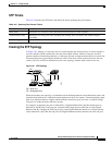
All switches in the Layer 2 network participating in STP gather information about other switches in the
network through an exchange of data messages called Bridge Protocol Data Units (BPDUs). This
exchange of messages results in these actions:
• The election of a unique root switch for each spanning-tree instance
• The election of a designated switch for every switched LAN segment
Table 10-1 Switch Priority Value and Extended System ID
Switch Priority Value Extended System ID (Set Equal to the VLAN ID)
Bit 16 Bit 15 Bit 14 Bit 13 Bit 12 Bit 11 Bit 10 Bit 9 Bit 8 Bit 7 Bit 6 Bit 5 Bit 4 Bit 3 Bit 2 Bit 1
32768 16384 8192 4096 2048 1024 512 256 128 64 32 16 8 4 2 1