


3-8
Catalyst 3550 Multilayer Switch Software Configuration Guide
78-11194-03
Chapter 3 Getting Started with CMS
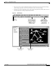
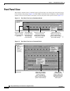
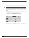
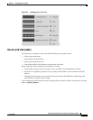
Front Panel View
Port Modes and LEDs
The port modes (Table 3-3) determine the type of information displayed through the port LEDs. When
you change port modes, the meanings of the port LED colors (Table 3-4) also change.
Note The bandwidth utilization mode (UTL LED) does not appear on the front-panel images. Select
Reports > Bandwidth Graphs to display the total bandwidth in use by the switch. Refer to the
switch hardware installation guide for information about using the UTL LED.
To select or change a mode, click the Mode button until the desired mode LED is green.
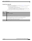
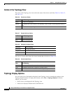
Table 3-3 Port Modes
Mode LED Description
STAT Link status of the ports. Default mode.
DUPLX Duplex setting on the ports.
SPEED Speed setting on the ports.
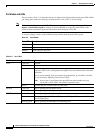
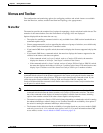
Table 3-4 Port LEDs
Port Mode Port LED Color Description
STAT Cyan (off) No link.
Green Link present.
Amber Link fault. Error frames can affect connectivity, and errors such as excessive
collisions, CRC errors, and alignment and jabber errors are monitored for a link-fault
indication.
Port is not forwarding. Port was disabled by management, by an address violation,
or was blocked by Spanning Tree Protocol (STP).
Note After a port is reconfigured, the port LED can remain amber for up to
30 seconds as STP checks the switch for possible loops.
Brown No link and port is administratively shut down.
DUPLX Cyan (off) Port is operating in half-duplex mode.
Green Port is operating in full-duplex mode.
SPEED Cyan (off) Port is operating at 10 Mbps or no link.
Green Port is operating at 100 Mbps (10/100 ports), 155 Mbps (ATM ports), or 1000 Mbps
(fixed Gigabit port).
Blinking green Port is operating at 1000 Mbps (10/100/1000 ports).