


20-16
Catalyst 3550 Multilayer Switch Software Configuration Guide
78-11194-03
Chapter 20 Configuring QoS
Understanding QoS
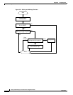
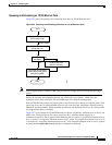
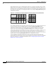
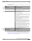
Each minimum-reserve level is configured with a buffer size. As shown in the figure, queue 4 of Fast
Ethernet port 0/1 has a buffer size of 70 packets, queue 4 of Fast Ethernet port 0/2 has a buffer size of
80 packets, queue 4 of Fast Ethernet port 0/3 has a buffer size of 40 packets, and Fast Ethernet port 0/4
has a buffer size of 80 packets. You configure the buffer size by using the mls qos min-reserve global
configuration command.
Figure 20-7 10/100 Ethernet Port Queue Assignment, Minimum-Reserve Levels, and Buffer Size
The available bandwidth of the egress link is divided among the queues. You configure the queues to be
serviced according to the ratio of WRR weights by using the wrr-queue bandwidth interface
configuration command. Queues are selected by the CoS value that is mapped to an egress queue
(CoS-to-egress-queue map) through the wrr-queue cos-map interface configuration command.
All four queues participate in the WRR unless the egress expedite queue is enabled, in which case, the
fourth bandwidth weight is ignored and not used in the ratio calculation. The expedite queue is a
strict-priority queue, and it is serviced until empty before the other queues are serviced. You enable the
expedite queue by using the priority-queue out interface configuration command.
You can combine the commands described in this section to prioritize traffic by placing packets with
particular DSCPs into certain queues, allocate a larger minimum-reserve buffer size, and service a particular
queue more frequently. For configuration information, see the “Configuring Egress Queues on 10/100
Ethernet Ports” section on page 20-51.
Fast Ethernet
Port Number
Q1
MRL*
1
2
1
5
Q2
MRL
3
4
2
6
Q3
MRL
5
6
3
7
Q4
MRL
7
8
4
8
0/1
0/2
0/3
0/4
•
•
•
MRL
1
2
3
4
5
6
7
8
Buffer size
10
20
30
40
50
60
70
80
65127
* MRL = Minimum-reserve level