


1-14
Catalyst 3550 Multilayer Switch Software Configuration Guide
78-11194-03
Chapter 1 Overview
Network Configuration Examples
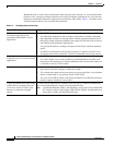
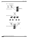
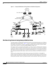
Figure 1-3 Catalyst 3550 Switches in Wiring Closets in a Backbone Configuration
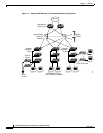
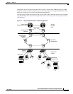
Multidwelling Network Using Catalyst 3550 Switches
A growing segment of residential and commercial customers are requiring high-speed access to Ethernet
metropolitan-area networks (MANs). Figure 1-4 shows a configuration for a Gigabit Ethernet MAN ring
using Catalyst 3550 multilayer switches as aggregation switches in the mini-point-of-presence (POP)
location. These switches are connected through 1000BASE-X GBIC ports.
The resident switches can be Catalyst 3550 switches, providing customers with high-speed connections
to the MAN. Catalyst 2912-LRE or 2924-LRE XL Layer 2-only switches also can be used as residential
switches for customers requiring connectivity through existing phone lines. The Catalyst 2912-LRE or
2924-LRE XL switches can then connect to another residential switch or to an aggregation switch. For
more information about the LRE switches, refer to the Catalyst 2900 Series XL Hardware Installation
Guide.
All ports on the residential Catalyst 3550 switches (and Catalyst 2912-LRE XL or 2924-LRE XL
switches if they are included) are configured as 802.1Q trunks with protected port and STP root guard
features enabled. The protected port feature provides security and isolation between ports on the switch,
ensuring that subscribers cannot view packets destined for other subscribers. STP root guard prevents
IP
Gigabit
servers
50832
Cisco IP
Phones
Cisco IP
Phones
Catalyst
3550
cluster
Catalyst
3550
cluster
Cisco 7500 routers
Catalyst 6000
multilayer switches
AC
power
source
WAN
IP
IP
IP IP
IP
Si Si
SiSi