


7000 Series Route Switch Processor (RSP7000) Installation and Configuration in the Cisco 7000 Series Routers 19
Installation Procedures
Step 3 If you are replacing the RSP7000, disconnect any devices that are attached to the console
or auxiliary ports. If you are removing the RSP7000 for maintenance and will reinstall the
same one, you can leave the devices attached provided that doing so will not strain the
cables.
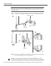
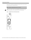
Step 4 Use a screwdriver (number 2 Phillips or 3/16-inch flat-blade) to loosen the two captive
installation screws. (See Figure 4 on page 20.)
Step 5 Place your thumbs on the ends of each of the ejectors and simultaneously pull them both
outward, away from the carrier handle (in the opposite direction from that shown in
Figure 4c) to release the carrier from the slot and to dislodge the RSP7000 from the
backplane.
Step 6 Grasp the handle with one hand and pull the RSP7000 straight out of the slot, keeping your
other hand under the carrier to guide it. (See Figure 4.) Keep the carrier parallel to the
backplane. Avoid touching the board or any connector pins.
Step 7 Place the removed RSP7000 on an antistatic mat or foam. If you plan to return the RSP7000
to the factory, immediately place it in an antistatic bag to prevent ESD damage.
This completes the removal procedure. If you removed the RSP7000 to replace SIMMs, proceed to
the appropriate section. If you are replacing the RSP7000, proceed to the next section to install the
new RSP7000.
Replacing the RSP7000
Ensure that all system power is turned off before installing the RSP7000 in the chassis. The
RSP7000 is keyed for installation only in the 7000 RSP slot. (See Figures 1 and 2.)
Follow these steps to install an RSP7000:
Step 1 Ensure that all power supplies are turned OFF.
Step 2 Grasp the RSP7000 handle with one hand and place your other hand under the carrier to
support and guide it into the slot. (See Figure 4.) Avoid touching the board or any
connectors.