


28 7000 Series Route Switch Processor (RSP7000) Installation and Configuration in the Cisco 7000 Series Routers
Reference Information
Reference Information
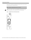
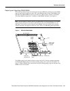
Following is reference information for console and auxiliary port pinouts, replacing DRAM SIMMs,
configuring the software configuration register, recovering a lost password, and using the front-panel
PCMCIA slots for additional Flash memory.
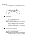
Console Port Signals
The console port on the RSP7000 is an EIA/TIA-232, DCE, DB-25 receptacle. Both DSR and DCD
are active when the system is running. The RTS signal tracks the state of the CTS input. The console
port does not support modem control or hardware flow control. The console port requires a
straight-through EIA/TIA-232 cable. Table 2 lists the signals used on this port.
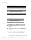
Table 2 Console Port Signals
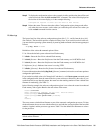
Auxiliary Port Signals
The auxiliary port on the RSP7000 is an EIA/TIA-232 DTE, DB-25 plug to which you can attach a
CSU/DSU or other equipment in order to access the router from the network. Table 3 lists the
EIA/TIA-232 signals used on this port.
The asynchronous auxiliary port supports hardware flow control and modem control.
Table 3 Auxiliary Port Signals
Pin Signal Direction Description
1 GND – Ground
2 TxD <— Transmit Data
3 RxD —> Receive Data
6 DSR —> Data Set Ready (always on)
7 GND – Ground
8 DCD —> Data Carrier Detect (always on)
Pin Signal Direction Description
2 TxD —> Transmit Data
3 RxD <— Receive Data
4 RTS —> Request To Send (used for hardware flow control)
5 CTS <— Clear To Send (used for hardware flow control)
6 DSR <— Data Set Ready
7 Signal Ground – Signal Ground
8 CD <— Carrier Detect (used for modem control)
20 DTR —> Data Terminal Ready (used for modem control)