


7000 Series Route Switch Processor (RSP7000) Installation and Configuration in the Cisco 7000 Series Routers 23
Troubleshooting the Installation
Use the following procedure to format a new Flash memory card:
Step 1 Insert the Flash memory card into slot 0. (If slot 0 is not available, use slot 1.)
Step 2 To format the Flash memory card, use the format slot0: (or format slot1:) command as
follows. (Use only Intel Series 2+ Flash memory cards.)
Router# format slot0:
All sectors will be erased, proceed? [confirm]
Enter volume id (up to 30 characters): MyNewCard
Formatting sector 1
Format device slot0 completed
Router#
Note For this example, an 8-MB Flash memory card was used, and at the line “Formatting sector,”
the system counted the card’s sectors backwards from 64 to 1 as it formatted them. For 16-MB Flash
memory cards, the system counts backwards from 128 to 1, and for 20-MB Flash memory cards, the
system counts backwards from 160 to 1.
The new Flash memory card is now formatted and ready to use.
Troubleshooting the Installation
This section contains procedures to follow if the system does not restart and boot as expected.
Review the descriptions that follow so you can anticipate the expected system startup sequence.
Then restart the system and try to isolate the problem by observing the LEDs as the system attempts
to boot the software and initialize the RSP7000 and each interface processor.
Verifying LEDs
Following are functional descriptions of the LEDs on the power supplies and processor modules, and
the behavior you should observe at system startup.
System Power LEDs
On the Cisco 7000 series routers, the DC LED is located on the power supply. If the DC LED goes
on and stays on, there is most likely a problem with the input power or one of the internal DC lines.
The DC LED will go on if the power supply reaches an out-of-tolerance voltage condition.The
power supply will shut down during startup if it detects an over-or undervoltage condition during
startup. For detailed descriptions of environmental monitoring functions, refer to the Cisco 7000
Hardware Installation and Maintenance or Cisco 7010 Hardware Installation and Maintenance
publications on UniverCD or in print.
RSP7000 LEDs
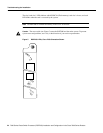
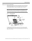
Figure 5 shows the LEDs on the RSP7000 faceplate. The LEDs on the RSP7000 indicate the system
and RSP7000 status and which Flash memory card slot is active. The CPU halt LED, which goes on
only if the system detects a processor hardware failure, should remain off. A successful boot is
indicated when the normal LED goes on; however, this does not necessarily mean that the system
has reached normal operation. During normal operation, the CPU halt LED should be off, and the
normal LED should be on.