


7000 Series Route Switch Processor (RSP7000) Installation and Configuration in the Cisco 7000 Series Routers 21
Installation Procedures
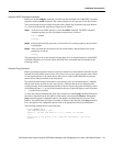
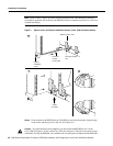
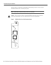
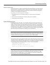
Step 4 While keeping the RSP7000 parallel to the backplane, carefully slide the carrier into the
7000 RSP slot until the RSP7000 faceplate makes contact with the ejector levers, then stop.
(See Figure 4b.)
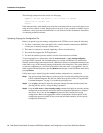
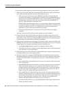
Step 5 Using the thumb and forefinger of each hand to pinch each ejector, simultaneously push
both ejectors inward (toward the handle) until they parallel to the faceplate. (See Figure 4c.)
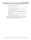
Step 6 Use a screwdriver (number 2 Phillips or 3/16-inch flat-blade) to tighten the captive
installation screws on the ends of the RSP7000. (See Figure 4a.)
Tighten the two captive screws on the RSP7000 faceplate to prevent the RSP7000 from
becoming partially dislodged from the backplane and to ensure proper EMI shielding.
(These screws must be tightened to meet EMI specifications.)
Step 7 If you disconnected the console terminal to remove the RSP7000, or if you are installing a
new RSP7000, connect the console terminal to the console port.
Step 8 Ensure that the console terminal is turned on.
Step 9 Turn the system power back ON, and proceed to the next section to check the installation.
Restarting and Checking the System
When you turn the system power back on, verify that the system boots and resumes normal
operation. If you are restarting the system after upgrading the DRAM expect that it will take the
system longer to complete the memory initialization portion of the boot sequence with more DRAM.
(See the section “System Startup Sequence” on page 25.)
Follow these steps to verify that the RSP7000 is installed and functioning properly:
Step 1 Check the RSP7000 connections to make sure they are secure:
• The RSP7000 is inserted all the way into its slot, and both of the captive installation
screws are tightened.
• The console terminal is turned on and is connected to the console port.
Step 2 Observe the RSP7000 LEDs. While the system initializes, the yellow boot error LED on
the RSP7000 stays on, then goes off when the boot is complete. As the RSP7000 initializes
each interface processor, the status LEDs on each interface processor go on and off in
irregular sequence.
Step 3 Verify that the console terminal displays the system banner and startup screen as the system
restarts. The display should look similar to the following:
Cisco Internetwork Operating System Software
IOS (tm) GS Software (RSP-K), 10.3(9), RELEASED SOFTWARE
Copyright (c) 1986-1996 by cisco Systems, Inc.
Compiled Wed 10-May-95
System Bootstrap, Version 5.3(9)
Current date and time is Sat 5-13-1995 21:38:35
Boot date and time is Thur 5-11-1995 15:32:28
[displayed text omitted from this example]