


7000 Series Route Switch Processor (RSP7000) Installation and Configuration in the Cisco 7000 Series Routers 29
Reference Information
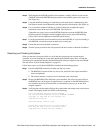
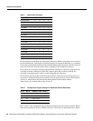
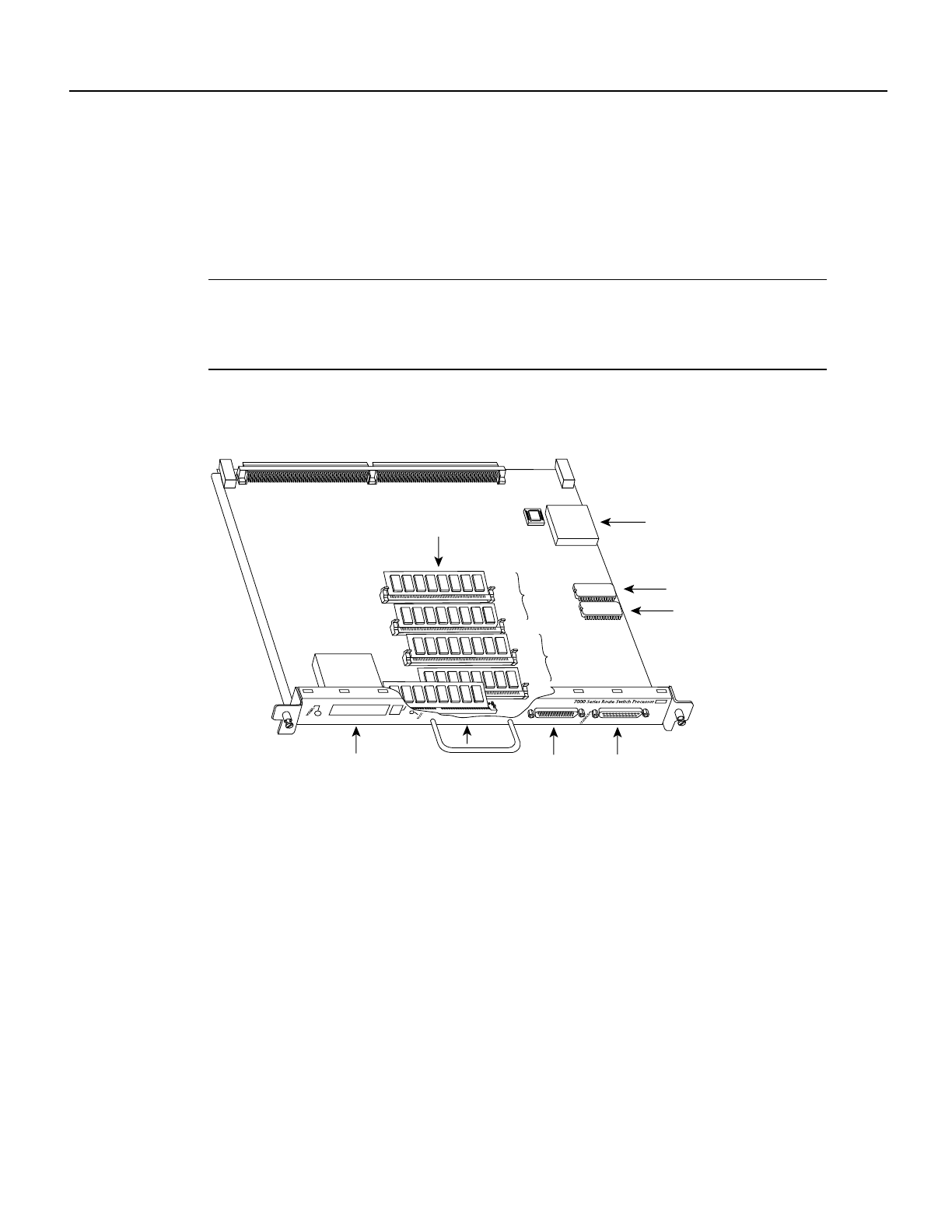
Replacing and Upgrading DRAM SIMMs
This section describes the steps for increasing the amount of DRAM by replacing up to four SIMMs
that you obtain from an approved vendor. The system DRAM resides on up to four SIMMs on the
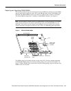
RSP7000. The DRAM SIMM sockets are U4 and U12 for Bank 0, and U18 and U25 for Bank 1.
The default DRAM configuration is 16 MB (two 8-MB SIMMs in Bank 0). (See Figure 6.)
Note The total number of memory devices per SIMM differs for each manufacturer. The SIMMs
in the following illustrations are generic representations of the actual DRAM SIMMs for your
RSP7000. To be sure that you are using the correct SIMMs, refer to the specific part or product
numbers indicated in the approved vendor list (AVL) and by your DRAM upgrade requirements.
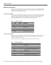
Figure 6 RSP7000 DRAM SIMMs
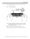
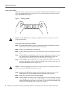
The SIMM sockets use the thumb tabs that are often used in PCs and other computer equipment.
Each RSP7000 SIMM socket has two metal retaining springs, one at each end. (See Figure 7 on
page 31.) When a SIMM is fully seated in the socket, the retaining springs snap over the ends of the
SIMM to lock it in the socket.
H5364
CPU
Flash SIMM
holder
Console port
Auxiliary port
NVRAM
Flash card
(PCMCIA) slot
DRAM
SIMMs
ROM monitor
(boot ROM)
U1
U4
U12
U18
U25
U24
U17
Bus connector
Bank 0
Bank 1