


8 7000 Series Route Switch Processor (RSP7000) Installation and Configuration in the Cisco 7000 Series Routers
Installation Prerequisites
Electrical Equipment
Follow these basic guidelines when working with any electrical equipment:
• Before beginning any procedures requiring access to the chassis interior, locate the emergency
power-off switch for the room in which you are working.
• Disconnect all power and external cables before moving a chassis.
• Do not work alone when potentially hazardous conditions exist.
• Never assume that power has been disconnected from a circuit; always check.
• Do not perform any action that creates a potential hazard to people or makes the equipment
unsafe.
• Carefully examine your work area for possible hazards such as moist floors, ungrounded power
extension cables, and missing safety grounds; correct all hazardous conditions.
Telephone Wiring
Use the following guidelines when working with any equipment that is connected to telephone
wiring or to other network cabling:
• Never install telephone wiring during a lightning storm.
• Never install telephone jacks in wet locations unless the jack is specifically designed for wet
locations.
• Never touch uninsulated telephone wires or terminals unless the telephone line has been
disconnected at the network interface.
• Use caution when installing or modifying telephone lines.
Preventing Electrostatic Discharge Damage
ESD damage, which can occur when electronic cards or components are improperly handled, results
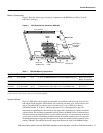
in complete or intermittent failures. Each processor module contains a printed circuit card that is
fixed in a metal carrier. Electromagnetic interference (EMI) shielding, connectors, and a handle are
integral components of the carrier. Although the metal carrier helps to protect the board from ESD,
use an ESD-preventive wrist or ankle strap whenever you handle any electronic system component.
Following are guidelines for preventing ESD damage:
• Always use an ESD-preventive wrist or ankle strap and ensure that it makes good skin contact.
• When you work at the interface processor end of the chassis, connect the equipment end of the
strap to the captive installation screw on an installed interface processor, or to any unfinished
chassis surface.
• When you install a processor module, use the ejector levers to properly seat the bus connectors
in the backplane, then tighten both captive installation screws. These screws prevent accidental
removal, provide proper grounding for the system, and help to ensure that the bus connectors are
seated in the backplane.
• Handle processor modules by the carrier handles and carrier edges only; never touch the board
or any connector pins.