2-6
Cisco UCS C220 Server Installation and Service Guide
OL-25760-01
Chapter 2 Installing the Server
Installing the Server In a Rack
Step 2 Install the slide rails onto the rack:
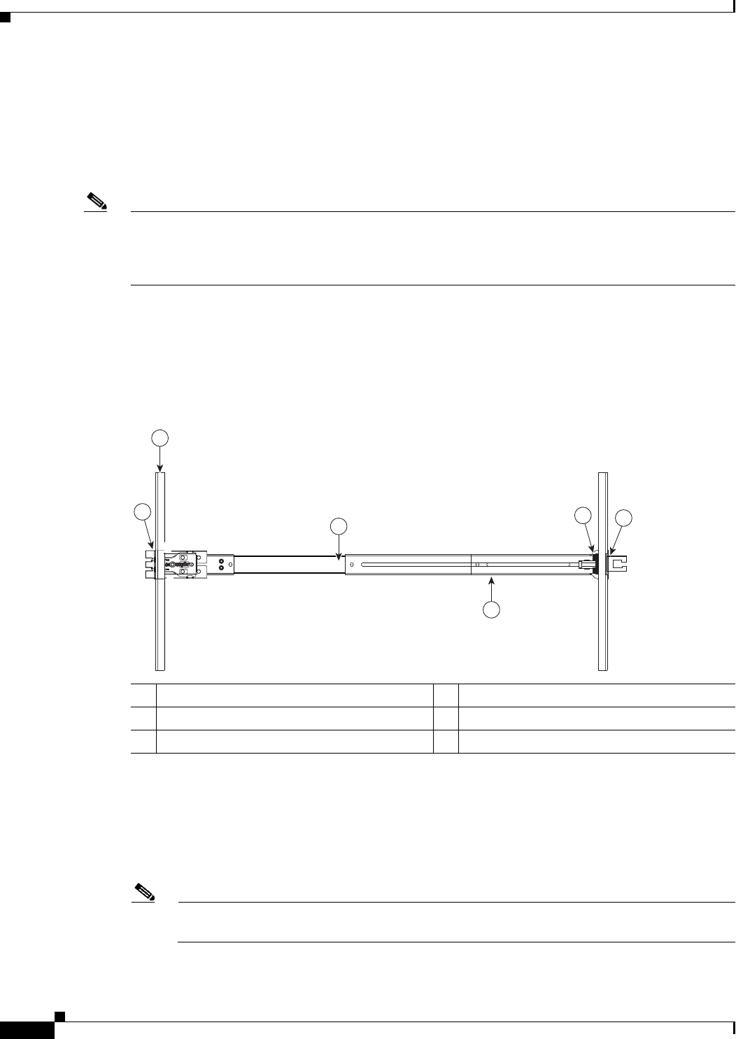
a. Position a slide-rail assembly inside the two left-side rack posts (see Figure 2-3).
Use the “FRONT” and “REAR” markings on the slide-rail assembly to orient the assembly correctly
with the front and rear rack posts.
b. Position the front mounting pegs so that they enter the desired front rack-post holes from the front.
Note The mounting pegs that protrude through the rack-post holes are designed to fit round or square holes,
or smaller #10-32 round holes when the mounting peg is compressed. If your rack has #10-32 rack-post
holes, align the mounting pegs with the holes and then compress the spring-loaded pegs to expose the
#10-32 inner peg.
c. Expand the length-adjustment bracket until the rear mounting pegs protrude through the desired
holes in the rear rack post.
Use your finger to hold the rear securing latch open when you insert the rear mounting pegs to their
holes. When you release the latch, it wraps around the rack post and secures the slide-rail assembly.
Figure 2-3 Attaching a Slide-Rail Assembly
d. Attach the second slide-rail assembly to the opposite side of the rack. Ensure that the two slide-rail
assemblies are level and at the same height with each other.
e. Pull the inner slide rails on each assembly out toward the rack front until they hit the internal stops
and lock in place.
Step 3 Insert the server into the slide rails:
Note The inner rails are pre-attached to the sides of the server at the factory. You can order
replacement inner rails if these are damaged or lost (Cisco PID UCSC-RAIL1-I).
a. Align the inner rails that are pre-attached to the server sides with the front ends of the empty slide
rails.
1 Front-left rack post 4 Length-adjustment bracket
2 Front mounting pegs 5 Rear mounting pegs
3 Slide-rail assembly 6 Rear securing latch


