


3-9
Cisco UCS C220 Server Installation and Service Guide
OL-25760-01
Chapter 3 Maintaining the Server
Preparing for Server Component Installation
Replaceable Component Locations
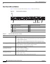
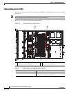
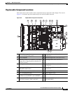
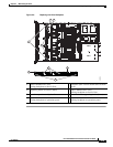
This section shows the locations of the components that are discussed in this chapter. The view in
Figure 3-5 is from the top down with the top cover and air baffles removed.
Figure 3-5 Replaceable Component Locations
1 Drives (hot-swappable,
accessed through front panel)
10 Trusted platform module socket on
motherboard
2 Drive backplane 11 Standard-height PCIe riser (PCIe slot 1)
3 Mounting location on air baffle for LSI battery
backup unit or SuperCap Power Module (air
baffle not shown)
12 Half-height PCIe riser (PCIe slot 2)
4 Cooling fan modules (five) 13 Cisco Flexible Flash card slot SD2 socket on
PCIe riser 2
5 SCU upgrade ROM header
(PBG DYNAMIC SKU)
14 Cisco Flexible Flash card slot SD1 socket on
PCIe riser 2
6 DIMM slots on motherboard (sixteen) 15 Internal USB 2.0 port
7 CPUs and heatsinks (two) 16 Power supplies (two)
8 Integrated RAID mini-SAS connectors on
motherboard, SASPORT 1 and SASPORT 2
17 RTC battery on motherboard
9 Mezzanine RAID card,
mini-SAS connectors SAS1 and SAS2
18 Software RAID 5 key header
(SW RAID KEY)
FAN1
FAN1
FAN1
FAN2
FAN2
FAN2
FAN3
FAN3
FAN3
FAN4FAN4
FAN4
FAN4
FAN5
FAN5
FAN5
PSU2
PCIe1
PCIe2
PSU1
CPU1
CPU2
SAS1
SAS2
SAS1
SAS2
1718
15
11
10
985
76
2 3
4
1
12
13
14
16