


3-47
Cisco UCS C220 Server Installation and Service Guide
OL-25760-01
Chapter 3 Maintaining the Server
Installing or Replacing Server Components
Replacing a SCU Upgrade ROM Module
To remove and replace a module, use the following procedure.
Step 1 Prepare the server for component installation:
a. Power off the server as described in Shutting Down and Powering Off the Server, page 3-7.
b. Slide the server out the front of the rack far enough so that you can remove the top cover. You might
have to detach cables from the rear panel to provide clearance.
Caution If you cannot safely view and access the component, remove the server from the rack.
c. Remove the top cover as described in Removing and Replacing the Server Top Cover, page 3-8.
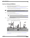
Step 2 Remove the SCU upgrade ROM module:
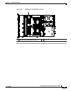
a. Locate the module on the motherboard (see Figure C-1).
b. Grasp the printed circuit board of the module and lift it from the header.
Note The module has a small retention feature that must have clearance from the header before
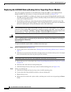
the module can be pulled up. Tilt the module back, then pull up as shown in Figure 3-26.
Step 3 Install a new SCU upgrade ROM module:
a. Align the module with the pins in the motherboard header.
b. Gently press down on the module until it is seated and the retention feature locks into the header.
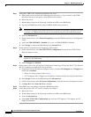
Figure 3-26 SCU Upgrade ROM Module Retention Feature
For more information about using the module and embedded RAID, see Embedded MegaRAID
Controller, page C-7.
1 Printed circuit board on module 3 Motherboard header
2 Retention feature on module 4 Retention feature in installed position
303690
3
4
2
1
1
2