


3-4
Cisco UCS C220 Server Installation and Service Guide
OL-25760-01
Chapter 3 Maintaining the Server
Status LEDs and Buttons
Rear Panel LEDs and Buttons
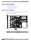
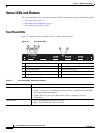
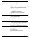
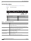
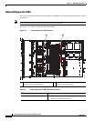
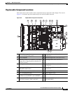
Figure 3-2 shows the rear panel LEDs and buttons. Table 3-2 defines the LED states.
Figure 3-2 Rear Panel LEDs and Buttons
1 Power supply fault LED 5 1-Gb Ethernet link speed LED
2 Power supply AC OK LED 6 1-Gb Ethernet link status LED
3 1-Gb Ethernet dedicated management link
status LED
7 Rear Identification button/LED
4 1-Gb Ethernet dedicated management link
speed LED
–
Ta b l e 3-2 Rear Panel LEDs, Definitions of States
LED Name State
Power supply fault • Off—The power supply is operating normally.
• Amber, blinking—An event warning threshold has been reached, but the power
supply continues to operate.
• Amber, solid—A critical fault threshold has been reached, causing the power
supply to shut down (for example, a fan failure or an over-temperature condition).
Power supply AC OK • Off—There is no AC power to the power supply.
• Green, blinking—AC power OK, DC output not enabled.
• Green, solid—AC power OK, DC outputs OK.
1-Gb Ethernet dedicated
management link speed
• Off—link speed is 10 Mbps.
• Amber—link speed is 100 Mbps.
• Green—link speed is 1 Gbps.
1-Gb Ethernet dedicated
management link status
• Off—No link is present.
• Green—Link is active.
• Green, blinking—Traffic is present on the active link.
PSU1PSU1 PSU2PSU2PSU1 PSU2
1
2 3 4 75 6
331692