


3-34
Cisco UCS C220 Server Installation and Service Guide
OL-25760-01
Chapter 3 Maintaining the Server
Installing or Replacing Server Components
Replacing a PCIe Card
Note If you are installing a Cisco UCS Virtual Interface Card, there are prerequisite considerations. See
Special Considerations for Cisco UCS Virtual Interface Cards, page 3-35.
Note If you are installing a RAID controller card, see RAID Controller Considerations, page C-1 for more
information about supported cards and cabling.
To install or replace a PCIe card, follow these steps:
Step 1 Remove a PCIe card (or a blank filler panel) from the PCIe riser:
a. Shut down and power off the server as described in the “Shutting Down and Powering Off the
Server” section on page 3-7.
b. Slide the server out the front of the rack far enough so that you can remove the top cover. You might
have to detach cables from the rear panel to provide clearance.
Caution If you cannot safely view and access the component, remove the server from the rack.
c. Remove the top cover as described in the “Removing and Replacing the Server Top Cover” section
on page 3-8.
d. Remove any cables from the ports of the PCIe card that you are replacing.
Tip Label the cables when you disconnect them to aid correct connection to the new card.
e. Lift straight up on both ends of the PCIe riser to disengage it from the socket on the motherboard.
f. Pull evenly on both ends of the PCIe card to remove it from the socket on the PCIe riser.
If the riser has no card, remove the blanking panel from the rear opening of the riser.
Step 2 Install a new PCIe card:
a. Align the new PCIe card with the empty socket on the PCIe riser.
Note Align and insert the card’s rear panel tab into the riser’s rear panel opening at the same time you
align the card with the empty socket.
b. Push down evenly on both ends of the card until it is fully seated in the socket.
c. Ensure that the card rear panel tab sits flat against the PCIe riser rear panel opening.
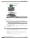
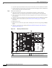
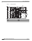
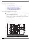
d. Position the PCIe riser over its socket on the motherboard and over the alignment features (see
Figure 3-21).
e. Carefully push down on both ends of the PCIe riser to fully engage its circuit board connector with
the socket on the motherboard.
f. Replace the top cover.
g. Replace the server in the rack, replace cables, and then power on the server by pressing the Power
button.