


3-31
Cisco UCS C220 Server Installation and Service Guide
OL-25760-01
Chapter 3 Maintaining the Server
Installing or Replacing Server Components
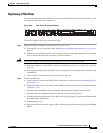
Replacing a PCIe Riser
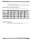
The server contains two toolless PCIe risers for horizontal installation of PCIe cards. See Table 3-6 for
a description of the PCIe slots on each riser.
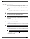
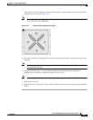
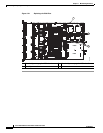
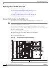
Figure 3-20 Rear Panel, Showing PCIe Slots
To install or replace a PCIe riser, follow these steps:
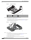
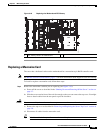
Step 1 Remove the PCIe riser that you are replacing (see Figure 3-19):
a. Power off the server as described in the “Shutting Down and Powering Off the Server” section on
page 3-7.
b. Slide the server out the front of the rack far enough so that you can remove the top cover. You might
have to detach cables from the rear panel to provide clearance.
Caution If you cannot safely view and access the component, remove the server from the rack.
c. Remove the top cover as described in “Removing and Replacing the Server Top Cover” section on
page 3-8.
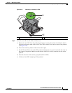
d. Lift straight up on both ends of the PCIe riser to disengage its circuit board from the socket on the
motherboard.
e. If the riser has a card installed, remove the card from the riser.
Step 2 Install a new PCIe riser:
a. If you removed a card from the old PCIe riser, install the card to the new riser (see Replacing a PCIe
Card, page 3-33).
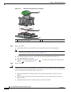
b. Position the PCIe riser over its socket on the motherboard and over the chassis alignment features
(see
Figure 3-19):
• The metal shell of the PCIe riser has alignment slots that engage with pegs on the chassis.
• The metal shell has alignment tabs that fit into slots on the chassis rear panel.
c. Carefully push down on both ends of the PCIe riser to fully engage its circuit board connector with
the socket on the motherboard.
d. Replace the top cover.
e. Replace the server in the rack, replace cables, and then power on the server by pressing the Power
button.
PSU1PSU1 PSU2PSU2PSU1 PSU2
331712
PCIe 2
PCIe 1