


3-14
Cisco UCS C220 Server Installation and Service Guide
OL-25760-01
Chapter 3 Maintaining the Server
Installing or Replacing Server Components
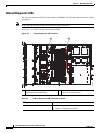
Replacing a Drive Backplane
Note The Small Form Factor (eight-drive) and Large Form Factor (four-drive) backplanes and their
corresponding chassis drive bays are factory-configurable options. When replacing a backplane, you
must replace it with the same version of the backplane.
To install or replace a drive backplane, follow these steps:
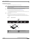
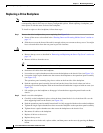
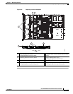
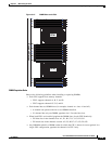
Step 1 Remove the drive backplane that you are replacing. See Figure 3-9:
a. Power off the server as described in the “Shutting Down and Powering Off the Server” section on
page 3-7.
b. Slide the server out the front of the rack far enough so that you can remove the top cover. You might
have to detach cables from the rear panel to provide clearance.
Caution If you cannot safely view and access the component, remove the server from the rack.
c. Remove the top cover as described in “Removing and Replacing the Server Top Cover” section on
page 3-8.
d. Remove all drives from the server.
Tip Label the drives as you remove them to aid replacement.
e. Disconnect all cables from the backplane.
f. Loosen the two captive thumbscrews that secure the backplane to the chassis floor (see Figure 3-9).
g. Loosen the single captive thumbscrew that secures the backplane to the operations panel assembly
(see
Figure 3-9).
The operations panel assembly plugs into a socket on the front side of the backplane.
h. Push the operations panel assembly forward and out the front of the chassis about one inch to
disengage it from the backplane. Push on the small metal handle that is engraved with an arrow (see
Figure 3-9).
i. Lift straight up on the backplane to disengage it from the three supporting metal hooks on the
chassis.
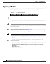
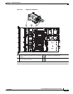
Step 2 Install a new drive backplane:
a. Carefully set the backplane in place so that the three slotted holes in its circuit board fit over the
three supporting hooks on the chassis (see
Figure 3-9).
b. Push the operations panel assembly inward until it is fully engaged with the socket on the backplane.
c. Tighten the single captive thumbscrew that secures the backplane to the operations panel assembly.
d. Tighten the two captive thumbscrews that secure the backplane to the chassis floor.
e. Reconnect all cables to the backplane.
f. Replace all drives to the server.
g. Replace the top cover.
h. Replace the server in the rack, replace cables, and then power on the server by pressing the Power
button.