


3-16
Cisco UCS C220 Server Installation and Service Guide
OL-25760-01
Chapter 3 Maintaining the Server
Installing or Replacing Server Components
Replacing Fan Modules
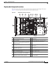
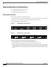
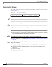
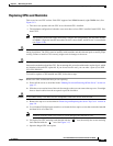
The five fan modules in the server are numbered as follows when you are facing the front of the server
(also see
Figure 3-11).
Figure 3-10 Fan Module Numbering
Tip Each fan module has a fault LED on the motherboard that lights amber if the fan module fails. Power
must be connected to the server for these LEDs to operate.
To replace or install a hot-pluggable fan module, follow these steps:
Caution You do not have to shut down or power off the server to replace fan modules because they are hot-
pluggable. However, to maintain proper cooling, do not operate the server for more than one minute with
any fan module removed.
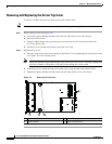
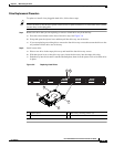
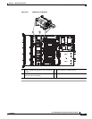
Step 1 Remove a fan module that you are replacing (see Figure 3-11):
a. Slide the server out the front of the rack far enough so that you can remove the top cover. You might
have to detach cables from the rear panel to provide clearance.
Caution If you cannot safely view and access the component, remove the server from the rack.
b. Remove the top cover as described in “Removing and Replacing the Server Top Cover” section on
page 3-8.
c. Grasp the fan module and lift straight up to disengage its connector from the motherboard.
Step 2 Install a new fan module:
a. Set the new fan module in place, aligning its two rubber dampening gaskets with the openings in the
chassis panel. See
Figure 3-11.
b. Press down gently on the fan module connector to fully engage it with the connector on the
motherboard.
c. Replace the top cover.
d. Replace the server in the rack.
FAN 1 FAN 2 FAN 3 FAN 4 FAN 5