


CF2001P
– 5 –
4004-7715-01
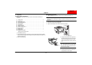
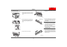
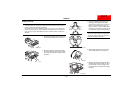
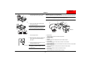
7. Remove the protective tape from the imag-
ing unit.
NOTE
The clear plastic protective sheet is not
packing material; therefore, do not remove
it.
* The additional protective sheet, indicated by
the shaded area, is only attached to the
black imaging unit.
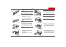
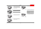
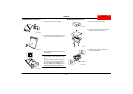
8. Keeping the imaging unit level, pick it up by
supporting it on the bottom with your left
hand and on the bottom at the front with your
right hand.
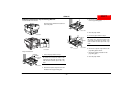
NOTE
When holding the imaging unit, be sure to
hold it by its bottom cover. If the top imaging
unit cover is held, it may fall off or the PC
drum installed on the imaging unit may
become damaged, resulting in decreased
image quality.
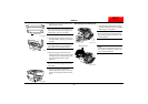
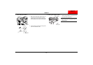
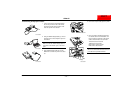
9. Keeping the imaging unit level, insert the
imaging unit as far as possible into the imag-
ing unit compartment.
Insert the imaging unit with the protective
sheet(s) attached.
NOTE
Be sure to insert the imaging unit until the
end of the bottom imaging unit cover con-
tacts the back of the imaging unit compart-
ment.
NOTE
Do not insert the imaging unit into the com-
partment at an angle.
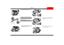
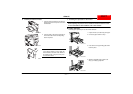
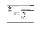
10. While keeping the bottom of the imaging unit
supported with your left hand, carefully
insert the imaging unit with your right hand,
as shown, until the cartridge snaps into
place.
11. Pull out the empty imaging unit cover.
The empty imaging unit cover for the black
imaging unit can simply be pulled out, even if
the protective sheets on the imaging unit
become caught on the toner hopper lid.
C4004U193AA
Protective sheet
*
C4004U215AB
C4004U216AB
C4004U051AC
C4004U052AB
C4004U217AB
C4004U053AB
C4004U054AB
NEXTNEXT