


CF2001P
– 6 –
4004-7715-01
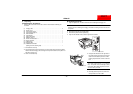
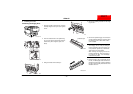
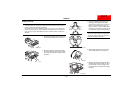
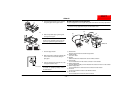
12. Separate the top and bottom halves of the
empty imaging unit cover.
NOTE
Since the bottom half of the imaging unit
cover will be used when the imaging unit is
replaced again, store it in a safe place.
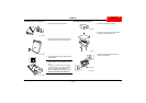
13. Carefully swing the release lever back up to
its original position, pushing it in until it locks
into place.
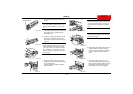
NOTE
If the release levers are not correctly posi-
tioned, the front door cannot be closed.
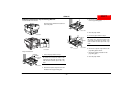
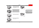
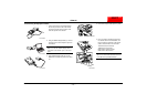
14. Remove the packing materials from the
remaining imaging unit slots, and then install
the magenta, cyan, and black imaging units
in the same way described in steps 2
through 13.
NOTE
Be sure to install the imaging units in their
correct slots.
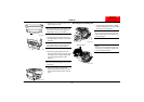
15. After all four imaging units have been
installed, grasp the handle of the front door,
and then carefully swing the door closed as
shown.
■
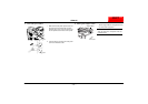
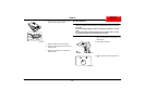
Installing the Oil-Coating Unit
1. Grasp the upper right-side door as shown,
and then carefully open the door completely
while making sure to support it.
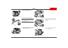
NOTE
Be sure to support the upper right-side door
while carefully opening it; otherwise, it may
become damaged.
NOTE
Do not touch the metal terminals at the front
of the fusing unit; otherwise, damage may
occur due to static electricity.
C4004U055AA
Bottom cover
C4004U056AA
C4004U013AA
C4004U173AA
C4004U149AB
Metal terminals
NEXTNEXT